


Page 3
MACRO range installation manual. Issue 6
Author: M. R. Tetley M. Inst. S. C. E.
________________________________________________________________________
INDEX
............................................................................................................................... page
Electromagnetic compatibility (EMC) directive 89/336/EEC and amendment directive 92/31/EEC
This equipment has been designed and manufactured to the highest standards. If connected and operated as set out in this manual, there should be no
Electromagnetic Compatibility problems. If any aspect of operation gives rise to concern, then please contact the manufacturer for advice.
Introduction ....................................................... ....................................................... 5
- The Company and its quality statement......................................... 5
- The MACRO system concept and applications ............................. 5
General specifications .............................................................................................. 6
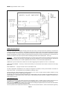
Front panel controls and indicators ................................ .......................................... 6
Tone control & Master gain adjustment ............................. ..................................... 6
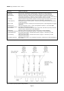
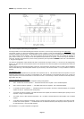
Input module system ............................................... ................................................ 7
- module installation .......................................................................... 7
- module range .................................................................................. 7
- features & general specifications ................................................... 8
- input connections ............................................................................ 9
- module adjustments........................................................................ 10
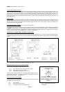
Priority input facilities .......................................... ..................................................... 10
- priority/passive setting of modules................................................. 12
- priority memory ............................................................................... 12
Pre-announcement chimes ............................................ .......................................... 12
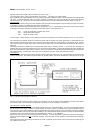
Mixer facility connections - 0dB signal access point .............. ................................. 12
- 0dB signal in/out access for mixers & mixer amplifiers ................. 12
- input connections for slave amplifiers ............................................ 12
- tape recording ................................................................................. 13
- tape playback .................................................................................. 13
- interconnection of several amplifiers ............................................. 13
Power amplifier module ............................................ ............................................... 14
Loudspeaker output ................................................. ................................................ 14
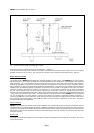
- typical loudspeaker load arrangements ......................................... 15
Auxiliary output connections ...................................... ............................................. 16
- Priority controlled DC current sinks ................................................ 16
- Chime duration monitor sinks (CDM) ............................................. 16
- 100V line output .............................................................................. 16
- 24V DC supply ................................................................................ 16
Combining the loudspeaker outputs of two or more amplifiers .................................. 17
Power supply ........................................................................................................... 17
- AC mains power input ..................................................................... 17
- DC power input ................................................................................ 17
- Systems powered by both AC and DC supplies ............................ 17
- Main ON-OFF front panel switch .................................................... 17
- Error status indicator LED .............................................................. 19
- Power status indicator LED ............................................................ 19
- Power supply failure monitoring ..................................................... 19
- Power supply change-over ............................................................. 20
- Battery charger circuit ..................................................................... 20
Earthing & hum loops .............................................. ................................................ 20
Factory fitted options ............................................ ................................................... 20
- Free-standing case ......................................................................... 20
- Automatic level control ................................................................... 21
- Balanced line input for M/100 and M/250 slave amplifiers............ 21
- Line surveillance ............................................................................. 22
Installation ...................................................... ......................................................... 22
- selection of signal input cables ...................................................... 22
- selection of loudspeaker cable ....................................................... 22
- fitting Locking DIN connectors ....................................................... 22
- siting ................................................................................................ 23
- ventilation ........................................................................................ 23
- interference ..................................................................................... 23
- removal of control knobs ................................................................ 23
- checklist .......................................................................................... 23
Fuses .......................................................... ............................................................ 24
Faults - symptoms and check-list ................................. .......................................... 24
Repairs and maintenance ........................................... ............................................ 24
- free-standing case removal ............................................................ 24
- removal of main pre-amplifier circuit board ................................... 24
Warranty .......................................................... ....................................................... 24