


DCA-600SSV — OPERATION AND PARTS MANUAL — REV. #0 (07/13/09) — PAGE 31
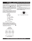
DCA-600SSV — GENERATOR OUTPUTS/GAUGE READING
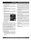
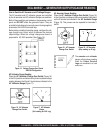
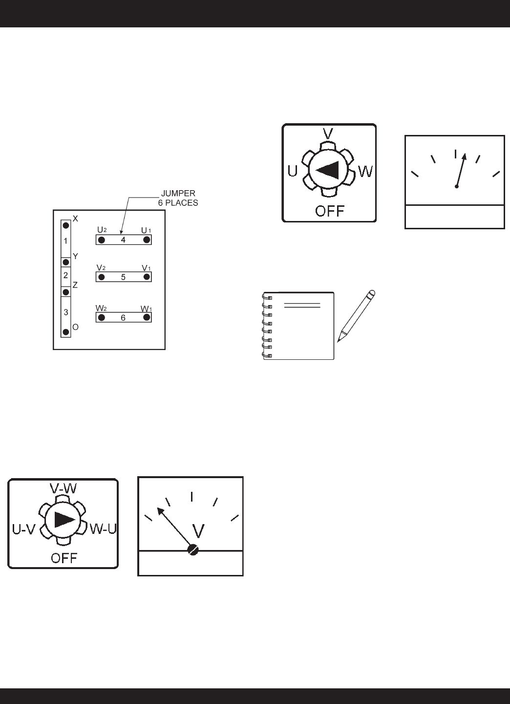
How to Read the AC Ammeter and AC Voltage Gauges.
The AC ammeter and AC voltmeter gauges are controlled
by the Ac ammeter and AC voltmeter change-over switches.
Both of these switches are located on the generator control
panel and DO NOT effect the generator output. They are
provided to help observe how much power is being supplied,
produced at the UVWO terminals lugs.
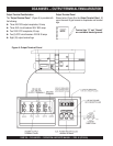
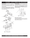
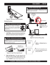
Before taking a reading from either gauge, configure the volt-
age change-over board which produces the desired
outputvoltage. When the voltage change-over board is
jumpered for 3Ø, 240V operation (See Figure 15).
The
ammeter
and
voltmeter
gauges will only show a reading
when the
Output Terminal
Lugs
are connected to a load
and in use.
NOTE
Figure 15. Voltage Change-Over Board
240V/3Ø Configuration
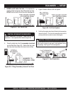
Figure 17 AC Voltmeter
Gauge
(Volt reading on W-U Lug)
Figure 16. AC Voltmeter
Change-Over Switch
A
0
40
60
75
20
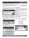
Figure 19. AC Ammeter
(Amp reading on U lug)
Figure 18. AC Ammeter
Change-Over Switch
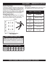
AC Voltmeter Gauge Reading
Place the
AC Voltmeter Change-Over
Switch
(Figure 16)
in the W-U position and observe the phase to phase voltage
reading between the W and U terminals as indicated in the
AC Voltmeter Gauge
(Figure 17).
AC Ammeter Gauge Reading
Place the
AC Ammeter Change-Over
Switch
(Figure 18)
in the U position and observe the current reading (load drain)
on the U terminal as indicated in the
AC Ammeter Gauge
(Figure 19). This process can be repeated for terminals V
and W.