


PAGE 16 — DCA250SSI 3-POSITION WHEEL GEN. • OPERATION AND PARTS MANUAL — REV. #0 (01/13/11)
GENERATOR
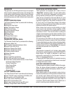
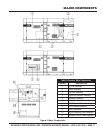
This generator is a 220 kW generator (Figure 3) equipped
with a 3-position voltage selector wheel, and is designed as
a high quality portable (requires a trailer for transport) power
source for telecom sites, lighting facilities, power tools,
submersible pumps and other industrial and construction
machinery.
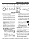
ENGINE OPERATING PANEL
The “Engine Operating Panel” is provided with the following:
Tachometer
Emergency Stop Switch
Water Temperature Gauge
Oil Pressure Gauge
Charging Ammeter Gauge
Fuel Level Gauge
Battery Switch
Pre-Heat Lamp
5 Engine Alarm Lamps
Engine Speed Switch
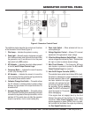
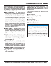
GENERATOR CONTROL PANEL
The “Generator Control Panel” is provided with the following:
Frequency Meter (Hz)
AC Ammeter (Amps)/AC Voltmeter (Volts)
Engine Control Unit (ECU)
Ammeter Change-Over Switch
Voltmeter Change-Over Switch
3-Position Selector Switch
Voltage Regulator
Pilot Lamp
Panel Light/Panel Light Switch
3-Pole, 800 amp Main Circuit Breaker
“Control Box” (located behind the Gen. Control Panel)
• Automatic Voltage Regulator
• Current Transformer
• Over-Current Relay
• Voltage Rectifi er
• Starter Relay
• Diagnostic Panel
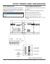
OUTPUT TERMINAL PANEL
The “Output Terminal Panel” is provided with the following:
Three 120/240V output receptacles (CS-6369), 50A
Three auxiliary circuit breakers, 50A
Two 120V output receptacles (GFCI), 20A
Two GFCI circuit breakers, 20A
Eight output busbar terminal lugs (3Ø power)
Battery Charger/Water Heater (Optional)
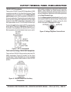
OPEN DELTA EXCITATION SYSTEM
These generators are equipped with a state of the art
“Open-Delta” excitation system. The open delta system
consist of an electrically independent winding wound
among stationary windings of the AC output section.
There are four connections of the open delta A, B, C and
D. During steady state loads, the power from the voltage
regulator is supplied from the parallel connections of A to
B, A to D, and C to D. These three phases of the voltage
input to the voltage regulator are then rectifi ed and are the
excitation current for the exciter section.
When a heavy load, such as a motor starting or a short
circuit occurs, the automatic voltage regulator (AVR)
switches the confi guration of the open delta to the series
connection of B to C. This has the effect of adding the
voltages of each phase to provide higher excitation to the
exciter section and thus better voltage response during the
application of heavy loads.
The connections of the AVR to the AC output windings are
for sensing only. No power is required from these windings.
The open-delta design provides virtually unlimited excitation
current, offering maximum motor starting capabilities. The
excitation does not have a “fi xed ceiling” and responds
according the demands of the required load.
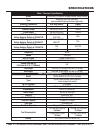
ENGINE
This generator is powered by a 6 cylinder, water cooled,
direct injection, turbocharged air-cooled ISUZU BH6UZ1X
diesel engine. The engine is designed to meet every
performance requirement for the generator. Reference
Table 1 for engine specifi cations.
In keeping with MQ Power’s policy of constantly improving
its products, the specifi cations quoted herein are subject
to change without prior notice.
ELECTRIC GOVERNOR SYSTEM
The electric governor system controls the RPMs of the engine.
When the engine demand increases or decreases, the
governor system regulates the frequency variation to ±.25%.
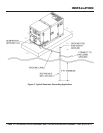
EXTENSION CABLES
When electric power is to be provided to various tools or
loads at some distance from the generator, extension cords
are normally used. Cables should be sized to allow for
distance in length and amperage so that the voltage drop
between the generator and point of use (load) is held to
a minimum. Use the cable selection chart (Table 6) as a
guide for selecting proper extension cable size.
GENERAL INFORMATION