


28 Section 7 — Service
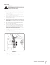
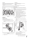
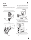
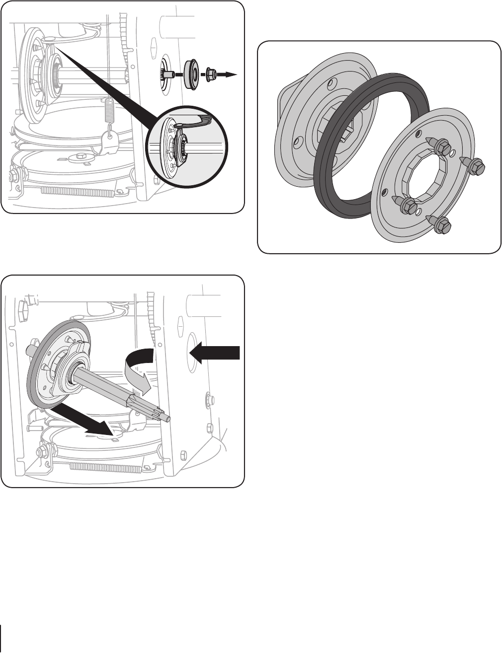
5. Carefully remove the hex nut which secures the hex shaft
to the snow thrower frame and lightly tap the shaft’s end to
dislodge the ball bearing from the right side of the frame.
See Figure 7-9.
NOTE: Be careful not to damage the threads on the shaft.
Figure 7-9
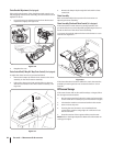
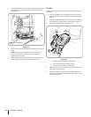
6. Carefully position the hex shaft downward and to the left
before carefully sliding the friction wheel assembly off the
shaft. See Figure 7-10.
Figure 7-10
NOTE: If you’re replacing the friction wheel assembly as a
whole, discard the worn part and slide the new part onto
the hex shaft.
7. Follow the previous steps in reverse order to reassemble
components.
8. Perform the Drive Control test on page 23 in the
Maintenance and Adjustments section.
If you’re disassembling the friction wheel and replacing only the
rubber ring, proceed as follows:
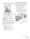
1. Remove the four screws which secure the friction wheel’s
side plates together. See Figure 7-11.
Figure 7-11
2. Remove the rubber ring from between the plates.
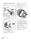
3. Reassemble the side plates with a new rubber ring.
NOTE: When reassembling the friction wheel assembly,
make sure that the rubber ring is centered and seated
properly between the side plates. Tighten each screw
only one rotation before turning the wheel clockwise
and proceeding with the next screw. Repeat this process
several times to ensure the plates are secured with equal
force (between 6 ft-lbs and 9 ft-lbs).
NOTE: Make sure the shift lever pin is in place in the
bearing housing. See Figure 7-9 inset.
4. Slide the friction wheel assembly back onto the hex shaft
and follow the steps above in reverse order to reassemble
components.
5. After replacing the friction wheel, perform the Drive
Control test on page 23 in the Maintenance and
Adjustments section.