


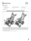
12 Section 3— ASSembly & Set-Up
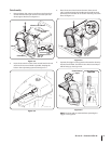
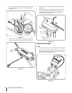
3. Finish securing chute control assembly to chute support
bracket with wing nut and hex screw removed earlier.
See Figure 3-14.
Figure 3-14
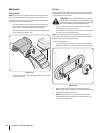
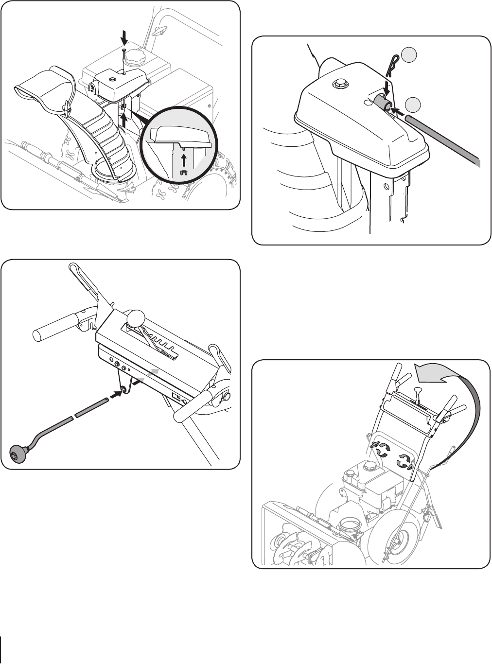
4. Insert the chute directional control rod into the support
bracket on the rear of the dash panel. See Figure 3-15.
Figure 3-15
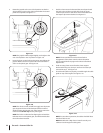
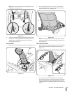
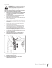
5. Remove the hairpin clip from the rear of the chute control
assembly.
6. Insert chute directional control rod into rear of the chute
control assembly. Secure the chute directional control
rod to the chute control assembly with the hairpin clip
removed earlier. See Figure 3-16.
1
2
Figure 3-16
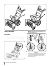
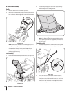
Standard Crank Assembly
Handle
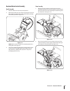
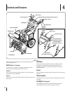
1. Place the shift lever in the forward-6 position (if equipped).
2. Observe the lower rear area of the snow thrower to be sure
both cables are aligned with roller guides before pivoting
the handle upward. See Figure 3-17.
Figure 3-17