


14 Section 3— ASSembly & Set-Up
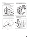
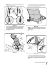
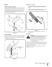
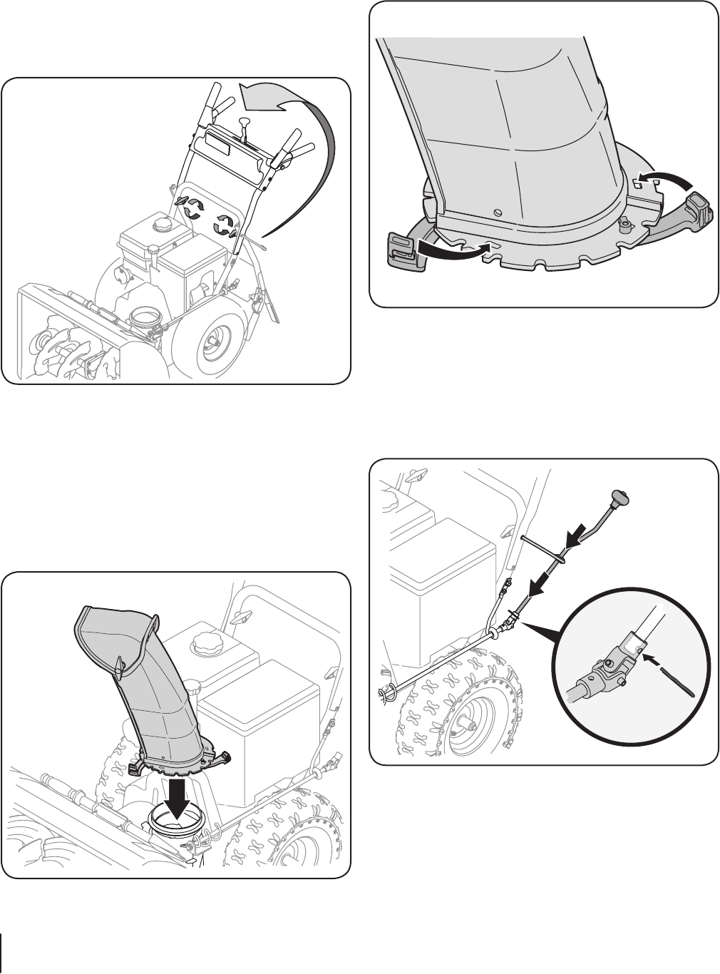
2. Close the flange keepers to secure the chute assembly
to the chute base. The flange keepers will click into place
when properly secure. See Figure 3-24.
Figure 3-24
NOTE: If the flange keepers will not easily click into place,
use the palm of your hand to apply swift, firm pressure to
the back of each.
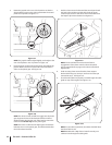
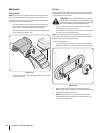
Chute Rod Assembly
1. Insert the unattached chute control rod into the eye bolt
on the left side of the handle assembly. See Figure 3-25.
Figure 3-25
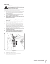
2. Line up the holes in the end of the unattached chute
control rod with the holes in the u-joint attached to the
lower chute control rod. Insert the cotter pin. See Figure
3-25. If necessary, the bracket securing the lower chute
control rod to the chute base can be adjusted. Refer to
Chute Bracket Adjustment in the Service section.
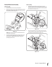
U-Joint Crank Assembly
Handle
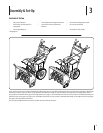
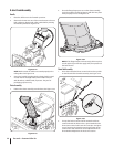
1. Place the shift lever in the forward-6 position.
2. Observe the lower rear area of the snow thrower to be sure
both cables are aligned with roller guides before pivoting
the handle upward. See Figure 3-22.
Figure 3-22
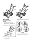
NOTE: Make certain the cables are seated properly in the
roller guides. See Figure 3-18.
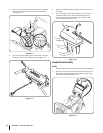
3. Secure the handle by tightening the plastic knob located
on both the left and right sides of the handle. Remove
and discard any rubber bands, if present. They are for
packaging purposes only.
Chute Assembly
1. Position the chute assembly over the base. See Figure 3-23.
Figure 3-23