


23Section 6 — Maintenance & adjuStMentS
Auger Control
Refer to the Assembly & Set-up section for instructions on
adjusting the auger control cable.
Skid Shoes
Refer to the Assembly & Set-up section for instructions on
adjusting the skid shoes.
Drive Control
When the drive control is released and in the disengaged “up”
position, the cable should have very little slack. It should NOT be
tight.
NOTE: If excessive slack is present in the drive cable or if the snow
thrower’s drive is disengaging intermittently during operation,
the cable may be in need of adjustment.
Check the adjustment of the drive control as follows:
1. With the drive control released, push the snow thrower
gently forward. The unit should roll freely.
2. Engage the drive control and gently attempt to push the
snow thrower forward. The wheels should not turn. The
unit should not roll freely.
3. If equipped with a shift lever, with the drive control
released, move the shift lever back and forth between the
R2 position and the F6 position several times. There should
be no resistance in the shift lever.
If any of the above tests failed, the drive cable is in need of
adjustment. Proceed as follows:
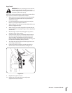
1. Shut off the engine as instructed in the separate engine
manual.
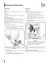
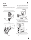
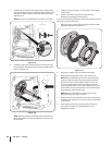
2. Loosen the lower hex screw on the drive cable bracket. See
Figure 6-5.
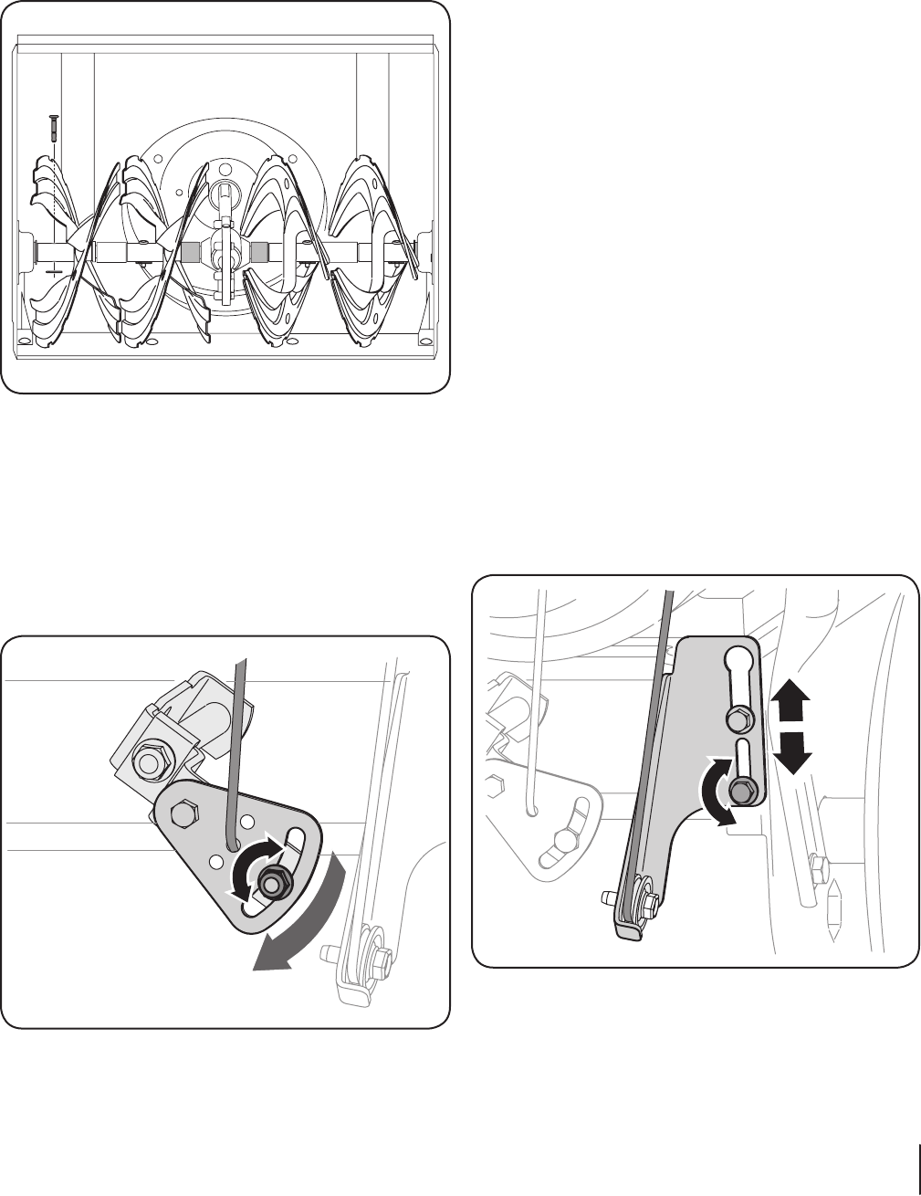
Figure 6-5
3. Position the bracket upward to provide more slack (or
downward to increase cable tension).
4. Retighten the upper hex screw.
5. Check the adjustment of the drive control as described
above to verify proper adjustment has been achieved.
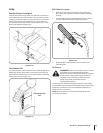
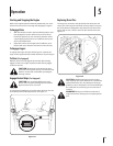
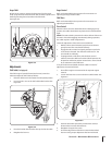
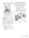
Auger Shaft
At least once a season, remove the shear pins from the auger
shaft. Spray lubricant inside the shaft and around the spacers and
the flange bearings found at either end of the shaft.
See Figure 6-3.
Figure 6-3
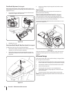
Adjustments
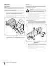
Shift Cable (If so Equipped)
If the full range of speeds (forward and reverse) cannot be
achieved, adjust the shift cable as follows:
1. Place the shift lever in the fastest forward speed position.
2. Loosen the hex nut on the shift cable index bracket. See
Figure 6-4.
Figure 6-4
3. Pivot the bracket downward to take up slack in the cable.
4. Retighten the hex nut.