


10 Section 3— ASSembly & Set-Up
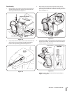
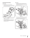
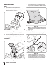
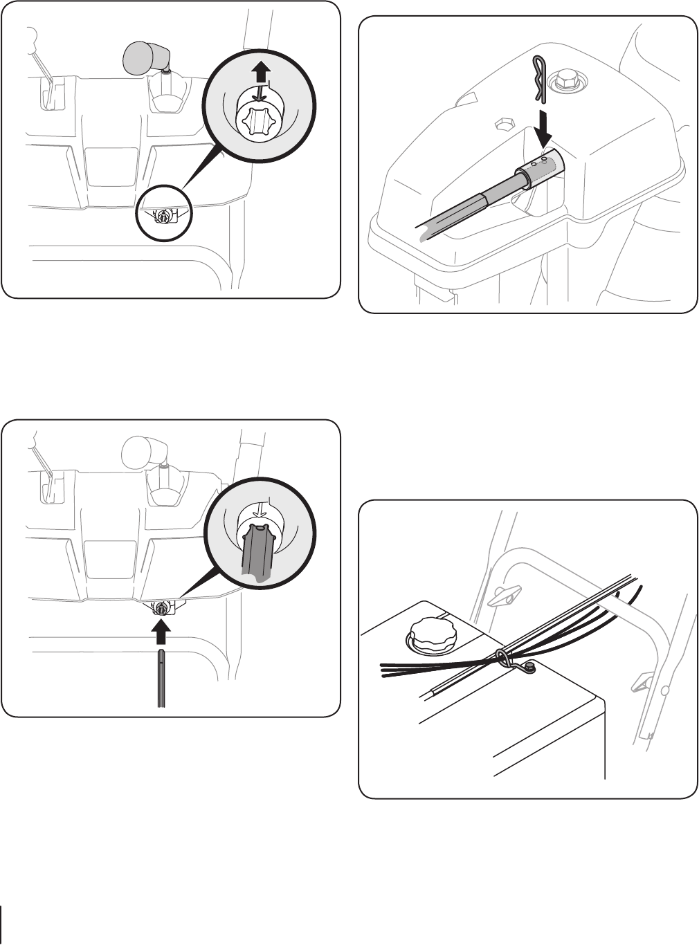
7. Push the chute control rod toward the control panel until
the hole in the rod lines up with the hole in the chute
control input closest to the chute control head and insert
the hairpin clip removed earlier. See Figure 3-9.
Figure 3-9
NOTE: The second hole is used to achieve further
engagement of the chute control rod into the pinion
gear if required. Refer to page 24 for Chute Control Rod
adjustments.
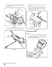
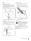
8. Finish securing chute control head to chute support
bracket with wing nut, clevis pin, and bow-tie cotter pin
removed in step 1. See Figure 3-3.
9. Check that all cables are properly routed through the cable
guide on top of the engine. See Figure 3-10.
Figure 3-10
NOTE: For smoothest operation, the cables should all be to
the left of the hex rod.
NOTE: Models with 2-Way Chute Control have only one
cable to route through the cable guide.
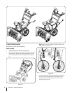
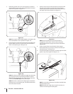
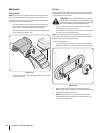
5. Rotate the joystick to the one o’clock position so that the
silver indicator arrow on the pinion gear below the control
panel faces upward. See Figure 3-7.
Figure 3-7
NOTE: The joystick will be angled slightly to the right at the
one o’clock position. See “Top View” in Figure 3-6.
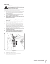
6. Insert the chute control rod into the pinion gear below the
joystick. Make sure to line up the hole in the rod with the
arrow on the pinion gear. See Figure 3-8.
Figure 3-8
NOTE: The chute control rod will fit snuggly into the pinion
gear. Support the rear of the dash panel with one hand
while inserting the rod with your other hand to ensure the
rod is inserted all the way into the pinion gear.
NOTE: The hole is a reference for aligning the rod with the
indicator arrow on the pinion gear, and will be visible after
the rod has been inserted.