


16 Section 3— ASSembly & Set-Up
Adjustments
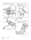
Chute Assembly
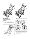
NOTE: Upper chutes on models with 4-Way Chute Control are
also controlled by the Chute Directional Control. See Fig. 4-1.
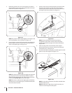
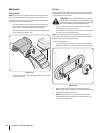
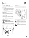
The distance snow is thrown can be adjusted by changing the
angle of the chute assembly. To do so:
1. Stop the engine. Refer to the Engine Operator’s Manual.
Remove the key from the engine and loosen the plastic
knob found on the left side of the chute assembly.
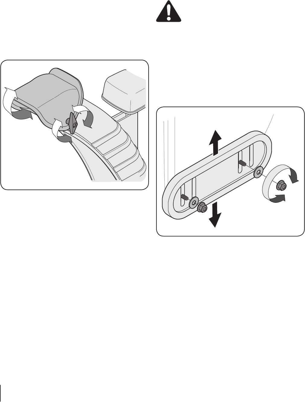
2. Pivot the chute upward or downward before retightening
the wing knob. See Figure 3-29.
Figure 3-29
3. Insert Key into engine and start engine. Refer to the Engine
Operator’s manual.
Skid Shoes
The snow thrower skid shoes are adjusted upward at the factory
for shipping purposes. Adjust them downward, if desired, prior
to operating the snow thrower.
CAUTION: It is not recommended that you operate
this snow thrower on gravel as it can easily pick up and
throw loose gravel, causing personal injury or damage
to the snow thrower and surrounding property.
• For close snow removal on a smooth surface, raise skid
shoes higher on the auger housing.
• Use a middle or lower position when the area to be cleared
is uneven, such as a gravel driveway
NOTE: If you choose to operate the snow thrower on a gravel
surface, keep the skid shoes in position for maximum clearance
between the ground and the shave plate.
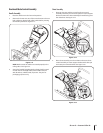
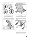
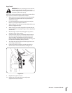
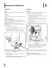
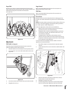
To adjust the skid shoes:
1. Loosen the four hex nuts (two on each side) and carriage
bolts. Move skid shoes to desired position. See Figure 3-30.
Figure 3-30
2. Make certain the entire bottom surface of skid shoe is
against the ground to avoid uneven wear on the skid shoes.
3. Retighten nuts and bolts securely.
NOTE: The skid shoes on your snow thrower may look
slightly different (and have different hardware) than the
ones shown in Figure 3-30.