


9
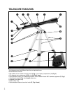
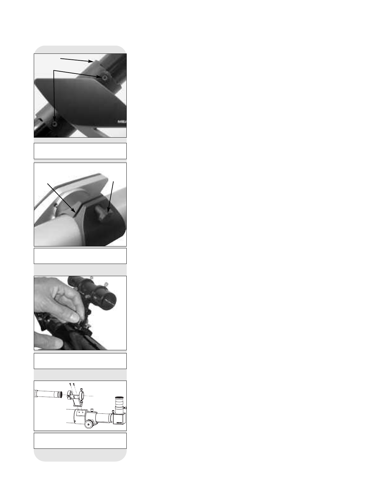
6. Insert the diagonal mirror and eyepiece: Insert the diagonal mirror (8, Fig. 1)
into the focuser drawtube (9, Fig. 1) and a low-power eyepiece (e.g., 25mm or
26mm eyepiece) into the diagonal mirror. Tighten the eyepiece and diagonal mir-
ror thumbscrews (
25 and 26, Fig. 4) to a firm feel.
Note: Some models are supplied with one of two styles of the 90° diagonal
mirror. Quantities of eyepieces and eyepiece size varies with each model.
7. Install battery (NGC Models Only): Lift the lid of the battery compartment (18,
Fig. 2
) and attach a 9v battery (user-supplied) to the connector provided in the
compartment.
8. Remove dust cap: Pull to remove the dust cap from the end of the telescope.
Replace it on the telescope at the end of the observing session. The cap keeps
the telescope lens free from dust and foreign particles when it is not in use.
Aligning the Viewfinder
Because the main telescope has a fairly narrow field of view, locating objects directly
in the main telescope can sometimes be difficult. The viewfinder (
6, Fig. 1) is a small,
wide-field telescope with crosshairs that permits you to more easily locate objects.
When the viewfinder and optical tube are aligned to each other, both point to the same
position in the sky. An object located in the viewfinder is therefore also positioned
within the field of the main telescope.
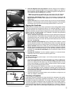
1.
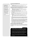
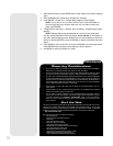
Attach viewfinder bracket (Style 1): Remove the two attachment thumbscrews
from the optical tube. These screws are pre-threaded at the factory into the opti-
cal telescope tube at the viewfinder location. Line up the holes in the viewfinder
bracket with the holes on the tube and thread the thumbscrews back onto the
main tube. See
Fig. 10a.
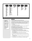
Attach viewfinder bracket (Style 2): Using a Phillips head screwdriver, thread
the two attachment screws in the bracket (these screws are placed inside the
bracket at the factory) into the mating threads on the optical tube. See
Fig. 10b.
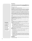
2. Attach viewfinder: Remove the rubber cup from the viewfinder tube and slide
the tube into the viewfinder bracket. Orient the viewfinder as depicted in Fig. 4.
Loosely tighten the collimation screws. You will use these screws to align the
viewfinder; see TO ALIGN THE VIEWFINDER, below. Re-attach the rubber cup onto
the viewfinder.
3. Focusing the Viewfinder: Turn the viewfinder eyepiece on its internal thread.
Generally a few turns are sufficient to achieve proper focus.
To Align the Viewfinder:
It is recommended that you perform steps 1 and 2 of this procedure during the day-
time and step 3 at night.
1. If you have not already done so, place a low-power (
e.g., 25mm or 26mm) eye-
piece in the diagonal mirror of the main telescope (8, Fig. 1) and point the tele-
scope at an easy-to-find land object (e.g., the top of a telephone pole). Turn the
focuser knob (
10, Fig. 1) so that the image is sharply focused. Center the object
precisely in the main telescope’s field of view.
2. Then, looking through the viewfinder, turn some or all of the viewfinder’s align-
ment screws (22, Fig. 4) until the viewfinder’s crosshairs point precisely at the
same object as centered in the main telescope. The viewfinder is now aligned to
the main telescope. Now tighten the screws to hold the tube securely; be careful
not shift the tube's alignment.
3. Check this alignment on a celestial object, such as the Moon or a bright star, and
make any necessary refinements.
Choosing an Eyepiece
A telescope’s eyepiece magnifies the image formed by the telescope’s main optics.
Each eyepiece has a focal length, expressed in millimeters, or "mm." The smaller the
focal length, the higher the magnification. For example, an eyepiece with a focal length
of 12.5mm has a higher magnification than an eyepiece with a focal length of 25mm.
Low-power eyepieces (
e.g., a 25mm or 26mm eyepiece) give a wide, comfortable field
of view with high image resolution. High-power eyepieces (
e.g., a 12.5mm or 4mm eye-
piece) provide a smaller field of view but higher magnification when seeing conditions
permit.
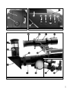
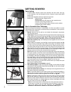
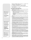
Fig. 9b: Attach optical tube to cradle
ring (Style 2).
Cradle
Lock
Knob
Fig. 10a: Attach viewfinder to the opti-
cal tube (Style 1).
Fig. 10b: Attach viewfinder to the opti-
cal tube (Style 2).
Fig. 9a: Attach optical tube to the
mount (Style 1).
Attachment
Nuts
Bracket