


8
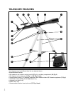
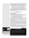
Parts Listing
• Complete 60mm diameter optical tube assembly with dew shield, dust cap,
5 x 24 viewfinder, and rack-and-pinion focuser; electronic control panel (NGC
models only).
• Continuously adjustable aluminum tripod and leg braces.
• Accessories: Eyepieces and 90° diagonal mirror
Accessory tray
3 screws (3/8" long) with wing nuts and screwdriver tool
3 screws (1 9/16" long) with hex nuts
2 nuts for attaching optical tube to bracket (certain models)
3 cylindrical pins (certain models)
How to Assemble Your Telescope
Note that although the telescope is unassembled, all of the more difficult or compli-
cated sections of the instrument are already factory pre-assembled. To set up the tel-
escope, follow this procedure:
1.
Identify: Remove from the gift box and identify the telescope’s components,
using the listing above.
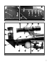
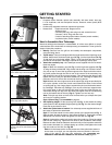
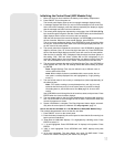
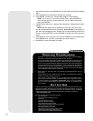
2. Tripod setup: The tripod is shipped with the tripod head and the tripod legs unat-
tached. Attach the 3 aluminum tripod legs (15, Fig. 1) to the tripod head (16, Fig.
1
) with the 3 leg locks facing inward. Three 1 9/16" long bolts and hex nuts are
provided for this purpose. See Fig. 5. Spread the tripod legs evenly apart.
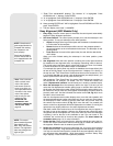
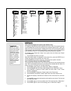
3. Attach the accessory tray: Your telescope comes supplied with one of two dif-
ferent tray styles.
Style 1: Attach the accessory tray (14, Fig. 1) to the leg brace supports (12, Fig.
1) using the three provided 3/8" long screws and the wing nuts. Place the acces-
sory tray on top of one of the leg brace supports of the tripod so that the mount-
ing screw passes through the hole at one of the corners of the accessory tray,
and through the slot in the leg brace support. Then thread-on the wing nut and
tighten the screw using the provided screwdriver tool. See
Fig. 6. Repeat this
procedure until all 3 corners are mounted to the 3 leg braces.
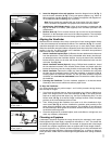
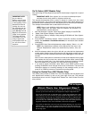
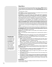
Style 2: Attach the inner support struts to the tripod legs using the provided pins.
Line up the cylinder on the end of each strut between the holes on the bracket
on each tripod leg. Use a large pliers to squeeze the pins into the bracket assem-
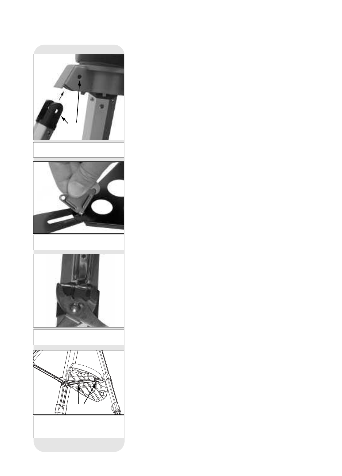
bly. See Fig. 7. Place the tray (14, Fig.1) over any one of the inner support struts.
Line up the bolts on the tray with the bolt holes on the strut. Slide the two pro-
vided bolts through the top of the bolt holes and tighten with the included wing
nuts on the bottom side of the tray (
Fig. 8). Tighten to a firm feel only.
Note: This style tray does not have to be removed when you collapse the tripod
at the end of a viewing session.
Style 3 (Round Tray): See APPENDIX B, page 24.
4. Set tripod leg height: Lift the tripod leg lock (13, Fig. 1) and extend the sliding
center portion of the adjustable height tripod leg (
15, Fig. 1) to the desired length.
Press the leg lock down to lock.
5. Attach the optical tube to bracket: Your telescope comes supplied with one of
two styles of optical tube attachment.
Style 1: Two bolts extend from the center portion of the optical tube (2, Fig. 1).
Slide the bolts through the holes in the bracket (3, Fig. 1). Thread the provided
attachment nuts over the bolts and tighten to a firm feel. See Fig. 9a.
Style 2: Unthread the cradle lock knob to open the cradle ring. Place the optical
tube into the cradle ring. Tighten the lock knob so that it holds the tube loosely.
Balance the tube: Slide the tube back and forth until you find a position where the
tube remains horizontal (
i.e., without tipping up or down). Now tighten the cradle
ring lock knob to a firm feel. See
Fig. 9b.
Note: If the horizontal and/or vertical movement of the optical tube seems to
be too loose or too tight, you can adjust the amount of tension in the move-
ment of the tube to suit your own preference. See ADJUSTING THE
HORIZONTAL AND VERTICAL TENSION OF THE OPTICAL TUBE
, page 20.
Fig. 5: Attach tripod legs to the tripod
head.
Fig. 6:Tighten screws with screwdriver
tool to attach tray to the struts (Style 1).
Fasten
wing nuts
Fig. 8: Attach tray to the tripod:Thread
the wing nuts to the bolts (bottom view;
Style 2).
Fig. 7: Attach pin to tripod leg bracket
with a large pliers (Style 2).
GETTING STARTED
Insert
bolt