


14 15
7 - MAINTENANCE INSTRUCTIONS
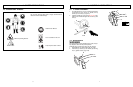
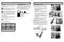
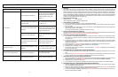
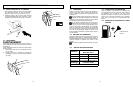
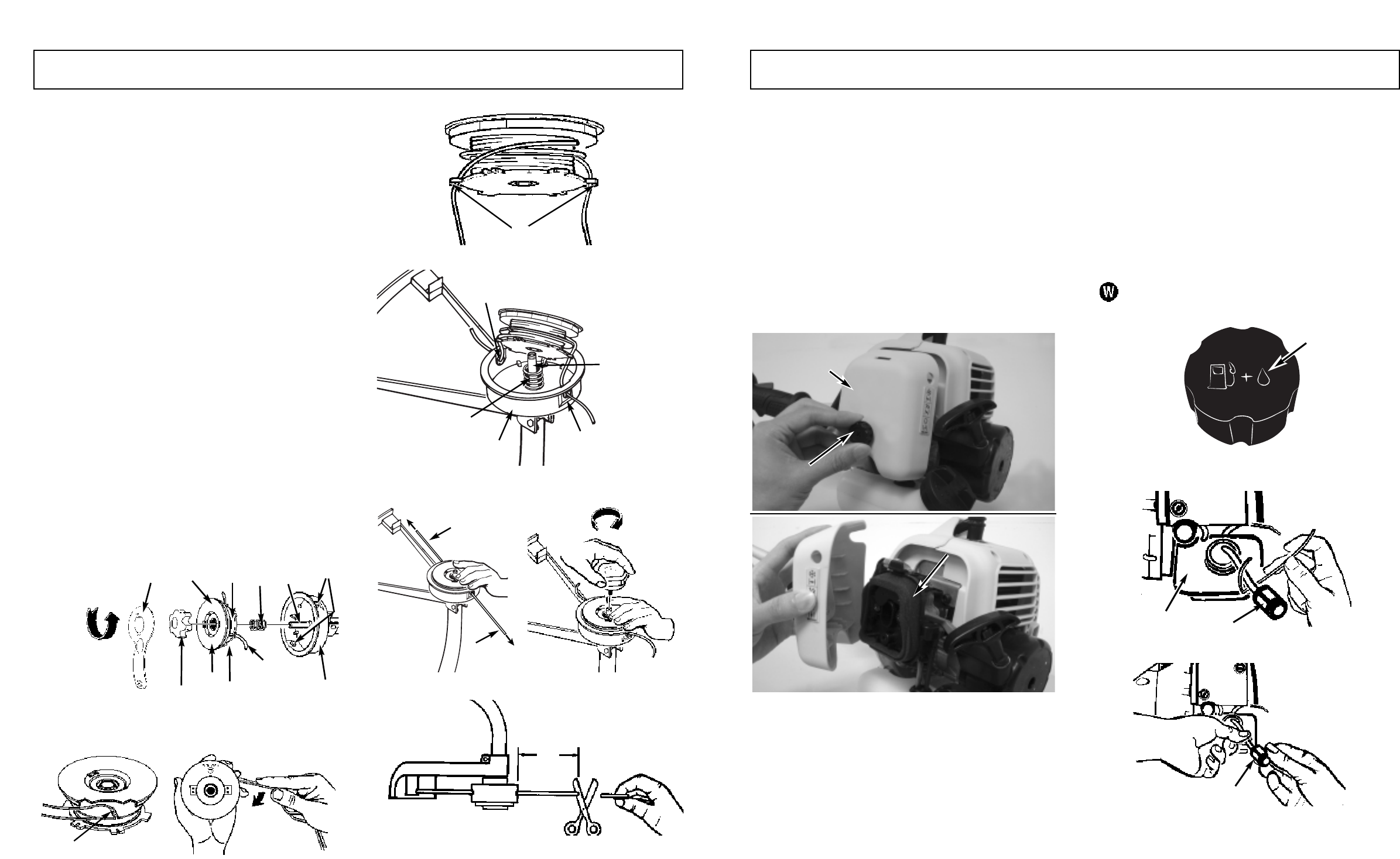
7-1. REPLACING CUTTING LINE
1. Turn knob (A) COUNTERCLOCKWISE and remove
(Figure 7-1A).
2. Remove spool (B) and spring (C) from spindle (D).
3. Remove any remaining cutting line (H).
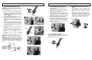
4. Fold over evenly a 14' (4.3m) length of .095 or .080"
(.24 or .20cm) cutting line. Place the looped center in
one of the slots (G) of the spool divider (Figure 7-1B).
5. Wind cutting line clockwise as shown in illustration
(Figure 7-1C), keeping tension, with each half sepa-
rated by the spool divider. Wind to within 6" (15cm) of
the ends.
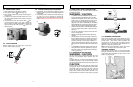
6. Lock each end of line into a slot (F) on opposite sides
of the spool (Figure 7-1D).
7. Install the spring (C) over the spindle (D). Insert each
end of the line through an eyelet (G) in the housing (E)
(Figure 7-1E).
8. Lower the spool into the housing (E) while feeding the
line through the eyelets (G). Ensure the spring seats
itself into the spool (Figure 7-1E).
9. Once the spool is in place, apply pressure on the
spool compressing the spring. Pull each end of the
line (H) sharply to unlock the line from the slots
(Figure 7-1F).
10. Continue to apply pressure to the spool until the knob
can be threaded CLOCKWISE onto the spindle.
Tighten the knob securely by hand only (Figure 7-1G).
11. Trim the excess line to approximately 5" (13cm). This
will minimize load on engine during starting and
warm-up (Figure 7-1H).
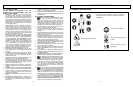
A.
KNOB
B.SPOOL
C.SPRING
D.SPINDLE
E.
HOUSING
F. SLOTS
G.EYELETS
H.CUTTING LINE
J. WRENCH
7-1A
7-1B
G
7-1C
J
C
D
F
H
G
A
B
F
H
E
7-1D
7-1E
F
7-1F 7-1G
H
H
7-1H
5"
(13mm)
G
C
D
E
G
7 - MAINTENANCE INSTRUCTIONS
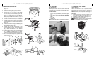
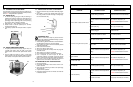
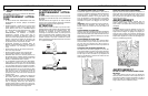
7-2. AIR FILTER
CAUTION
NEVER oper
ate trimmer without the air filter. The air filter
must be kept clean. If it becomes damaged, install a new fil-
ter.
To Clean Air Filter:
1. Remove knob (A) holding air filter cover in place,
remove cover (B) and lift filter (C) from air box (Figure
7-2A).
2. Wash filter in soap and water. DO NOT USE GASO-
LINE!
3. Air dry filter.
4. Reinstall filter.
NOTE: Replace filter if frayed, torn, damaged or unable to
be cleaned.
7-3. FUEL CAP / FUEL FILTER
CAUTION
Remo
ve fuel from unit and store in approved container
before starting this procedure. Open fuel cap slowly to
release any pressure which may have formed in fuel tank.
NOTE: Keep vent (A) on fuel cap clean of debris (Figure 7-
3A).
Fuel Filter:
1. Completely remove fuel cap from fuel tank (B) to be
able to remove fuel filter (C) from tank. (Figure 7-3B)
2. Pull filter (D) off with a twisting motion. (Figure 7-3C)
3. Replace fuel filter (D). (Figure 7-3C)
NOTE: Never operate the trimmer without the fuel fil-
ter. Internal engine damage could result!
7-2A
A
B
C
7-3A
A
7-3B
B
C
7-3C
D