


2 3
PLEASE READ
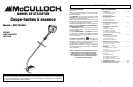
Dear Customer,
Thank you for purchasing a McCulloch product. With prop-
er operation and maintenance, it will provide you with years
of service.
In order to make the best use of your investment, be CER-
TAIN to familiarize yourself with the contents of the
ENTIRE user manual before attempting to operate and
maintain your unit.
Be sure to carefully follow the step-by-step instructions in
this manual to start, operate and maintain your new prod-
uct.
In the manual there will be the following call-outs: NOTE:,
WARNING / CAUTION and WARRANTY.
A NOTE: is used to convey additional information, to high-
light a particular explanation, or to expand a description.
A WARNING or CAUTION identifies a procedure which, if
not undertaken or if improperly done, can result in serious
personal injury and/or damage to the unit.
The (WARRANTY SYMBOL) serves notice that unless
instructions or procedures are followed, any damage
caused will void the warranty and repairs will be at owner’s
expense.
Pay particular attention to the safety precautions. They are
written for your protection and contain important informa-
tion you must know to safely operate your trimmer.
FOR WARRANTY OR SERVICE CONTACT THE NEAREST
McCULLOCH AUTHORIZED SERVICE CENTER - LOCATE
YOUR NEAREST SERVICE CENTER BY CALLING THE
TOLL FREE NUMBER IN THIS MANUAL.
TABLE OF CONTENTS
1 GENERAL INFORMATION . . . . . . . . . . . . . . . . . . . . . . . . . .2
1-1. General Identification
1-2. Safety Features
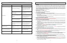
1-3. Specifications
2
SAFETY PRECAUTIONS . . . . . . . . . . . . . . . . . . . . . . . . . . . .4
2-1. What To Do
2-2. What Not To Do
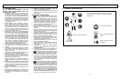
2-3. International Symbols
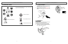
3 ASSEMBLY INSTRUCTIONS . . . . . . . . . . . . . . . . . . . . . . . . .6
3-1. “P” Handle Assembly
3-2. Debris Shield
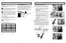
4 FUEL AND LUBRICATION . . . . . . . . . . . . . . . . . . . . . . . . . .8
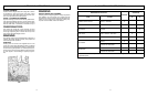
4-1. Fuel
4-2. Mixing Fuel
4-3. Fuel Mixing Table
4-4. Recommended Fuels
4-5. Fuel and Lubrication Symbols
5 OPERATING INSTRUCTIONS . . . . . . . . . . . . . . . . . . . . . . . .9
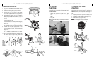
5-1. Starting a Cold Engine
5-3. To Stop Engine
5-2. Warm Engine Start
5-4. Idling/Carburetor Adjustment
6 TRIMMING INSTRUCTIONS . . . . . . . . . . . . . . . . . . . . . . . .11
6-1. Additional Safety Precautions
6-2. Stringhead Line Release
6-3. Trimming Procedures
7 MAINTENANCE INSTRUCTIONS . . . . . . . . . . . . . . . . . . . .13
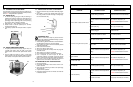
7-1. Replacing Cutter Line
7-2. Air Filter
7-3. Fuel Cap / Fuel Filter
7-4. Carburetor Adjustment
7-5.
Spar
k Plug
7-6. Spark Arrester Screen
7-7. Debris Shield Knife Sharpening
7-8. Storing a Unit
7-9. Removing a Unit From Storage
8 TROUBLESHOOTING THE ENGINE . . . . . . . . . . . . . . . . . .17
9 TROUBLESHOOTING THE STRINGHEAD . . . . . . . . . . . . .18
10 ONE YEAR LIMITED WARRANTY . . . . . . . . . . . . . . . . . . .19
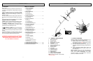
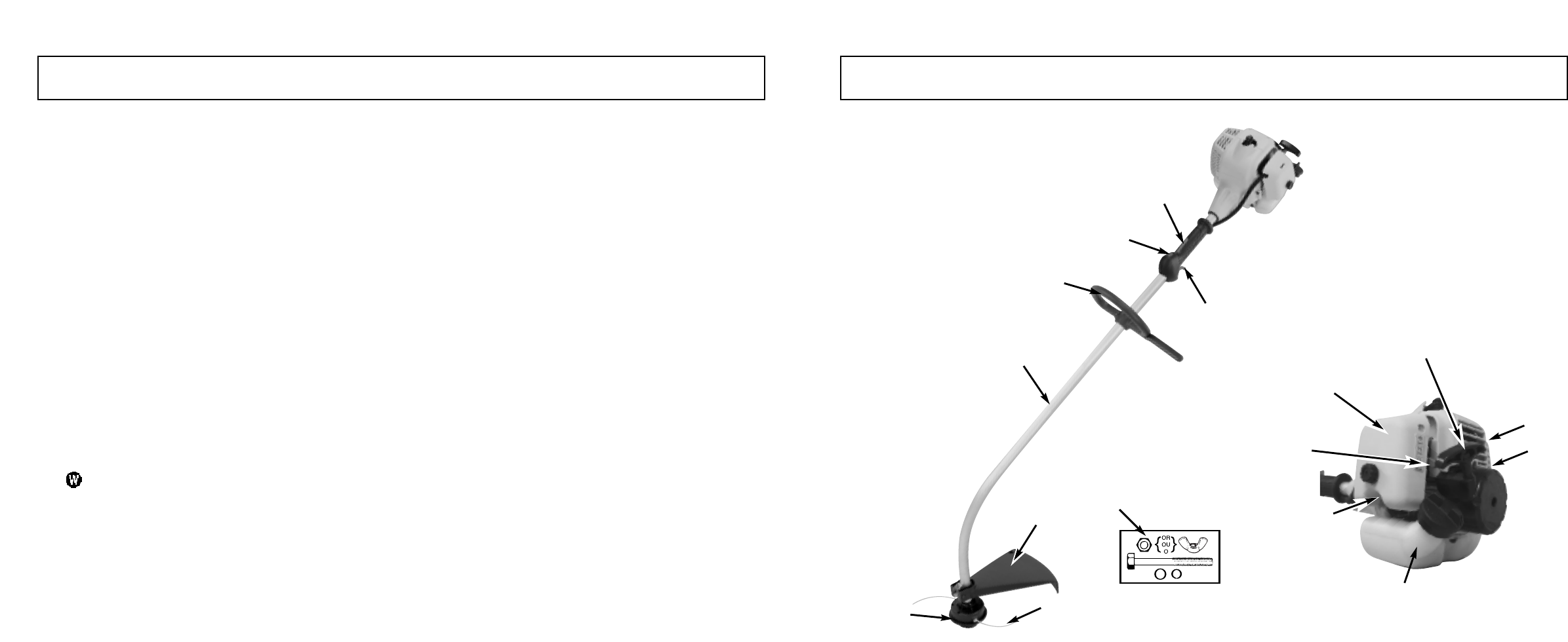
INTRODUCTION 1 - GENERAL INFORMATION
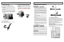
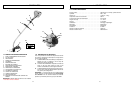
1-1. GENERAL IDENTIFICATION
1.
B
UMP FEED HEAD*
2.
CUTTING LINE
*
3. DEBRIS SHIELD*
4.
DRIVE SHAFT ASSEMBL
Y
5.
P-HANDLE
6. THROTTLE TRIGGER
7.
IGNITION ON/OFF SWITCH
8.
SAFETY
TRIGGER
9. CHOKE LEVER
10.
FUEL TANK
11.
AIR FIL
TER CO
VER
12. STARTER HANDLE
13.
MUFFLER SHIELD
14.
PRIMER B
ULB
15. SPARK ARRESTER SCREEN*
16. DEBRIS SHIELD HARDWARE
NO
TE:
DO NO
T use b
lades on these models.
* items are w
ear/m
1-2. SAFETY FEATURES
Numbers preceding the descriptions correspond to num-
bers above to help you locate the safety feature.
3 DEBRIS SHIELD m
ust be installed to prevent debris
from being thrown at the user and prevent the string
from extending longer than necessary.
13 MUFFLER SHIELD helps prevent hands, body and/or
combustible materials from making contact with a hot
muffler.
15 SPARK ARRESTER SCREEN retains carbon and
other flammab
le particles over 0.023" (.6 mm) in size
from e
xhaust flo
w
.
NOTE: Compliance with local, state and federal laws
and/or regulations governing the use of a spark arrester
screen is the user’s responsibility. See Safety
Precautions (Section 3) and Maintenance Instructions
(Section 8) for additional information.
1
3
2
4
5
6
7
8
11
12
13
10
14
9
16
15