


6
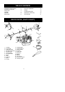
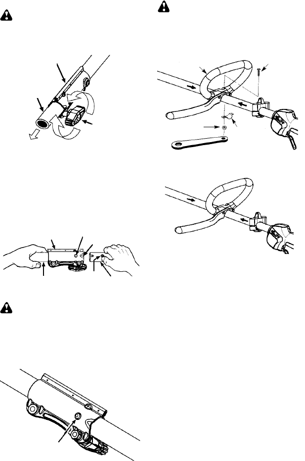
INSTALLING TRIMMER
ATTACHMENT
WARNING: When installing attach-
ment,placetheunit onaflatsurfaceforstabil-
ity.
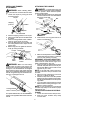
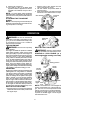
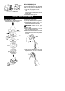
1. Loosen the coupler by turning the knob
counterclockwise.
Shipping
protector
Coupler
Knob
LOOSEN
TIGHTEN
2. Remove shipping protector from coupler .
3. Remove the shaft cap from the attachment
(if present).
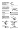
4. Position locking/release button of a ttach-
ment into guide recess of coupler.
5. Push theattachmentintothe coupleruntil
the locking/release button snaps into the
primary hole.
6. Before using the unit, tighten the knob se-
curely by turning clockwise.
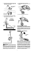
Coupler
Primary Hole
Upper
Shaft
Locking/
Release
Button
Attachment
Guide Recess
WARNING: Make sure the locking/
release button is locked in the primary hole
andthe knobis securely tightenedbefore op-
erating the unit. All attach ments are designed
to be used inthe primary hole unless otherwise
stated in the applicable attachment instruction
manual. U singthe wronghole couldleadtoseri-
ous injury or damage to the unit.
Locking/Release
Button in Primary Hole
For optiona l a ttachmen ts, see th e ASSEMBL Y
section of the applicable attachment instruction
manual.
ATTACHING THE HANDLE
DANGER: To avoid serious injury, the
barrier po rtion o fthe hand lemust beinstalled a s
shown to provide a barrier between operator
and the spinning blade.
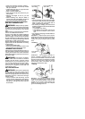
1. Position the loop handle on the shaft. Note
that the handle must be mounted between
the arrows on the shaft.
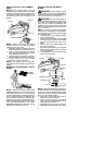
Wrench
Handle
Bolt
Securing
plate
Nut
2. Install the bolt, securing plate and nut as
shown in the illustration.
3. Make afinal adjustmentof thehandletoa
comfortableworkingposition. Tightenthe
nut firmly with wrench (provided).
ASSEMBLY OF SHOULDER STRAP
Proper shoulder strap and handlebar adjust-
ments must be made with the engine com-
pletely stopped before using unit.
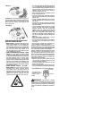
1. Insertyourrightarmandheadthroughthe
shoulder strap andallow it torest onyour
left shoulder. Make surethe hookis tothe
right side of your waist.
NOTE: A one-half twist is built in the shoul-
der strap to allow the strap to rest flat on the
shoulder.
2. Adjust the strap, allowing the hook to be
about 15 cm below the waist.
3. Fasten the strap hook to the clamp located
between the trigger handle and the handle-
barclampbaseand li ftthe t oolto t heoperat-
ing position.
4. Tryonshoulderstrapandadjustforfitand
balance before starting the engine or be-
ginning a cutting operation.
NOTE: Itmay be necessary to relocate the
shoulder strap clamp on the shaft for proper
balancing of unit.
TO RELOCATE SHOULDER STRAP
CLAMP:
1. Loosen and remove both clamp screws.
2. Place the upper shoulder strap clamp
over the shaft.