


10
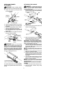
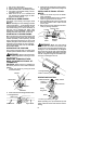
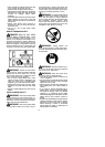
1. Set unit on a flat surface.
2. Slowly press the primer bulb 6 times.
3. Move the start l e ver to t he START position.
4. Pull starter rope handle sharply until en -
gine starts and runs.
5. Allow unit to run for 10--15 seconds, then
fully squeeze the throttle trigger to disen-
gage the starting system.
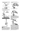
STARTING A WARM ENGINE
Pull starter rope sharply until engine starts
and runs.
NOTE:Normally, the warm starting procedure
can be u sed within 5 -- 10 minutes after the unit
is turnedoff. Ifthe unitsits for morethan 10min-
utes without being run, it will be necessary to
start the unit by following the steps under
STARTINGACOLDENGINEorfollowingthe
starting instruction steps shown on the unit.
STARTING A FLOODED ENGINE
Move the start lever to the RUN position and
fully squeeze throttle trigger. Pull the starter
handle repeatedly while squeezing throttle
triggeruntilenginestartsandruns.This could
require pullingthe starter handlemany times,
depending on how badly the unit is flooded.
If the unit still doesn’t start, refer to TROUBLE-
SHOOTING TABLE.
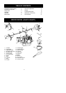
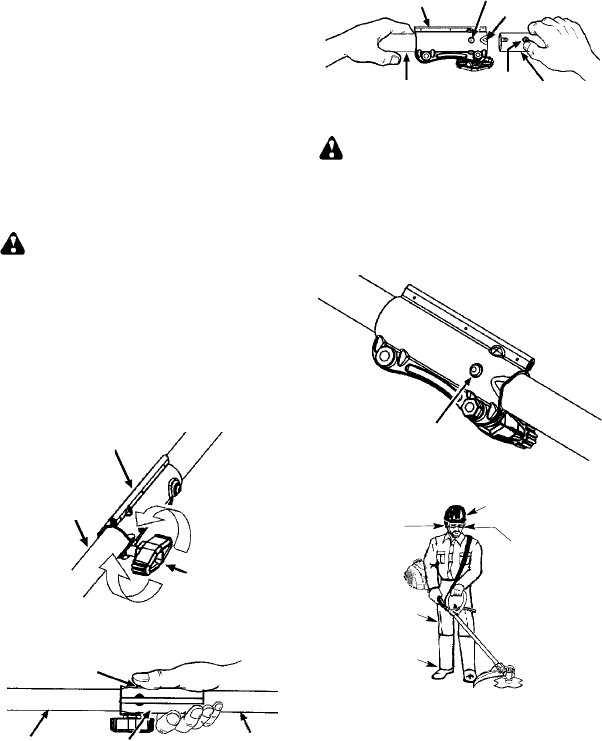
OPERATING THE COUPLER
This model is equipped with a coupler which
enables optional attachments to be installed.
WARNING: Always stopunitanddis-
connect sparkplug beforeremoving orinstal-
ling attachments.
REMOVING TRIMMER ATTACH-
MENT (OR OTHER OPTIONAL AT-
TACHMENTS)
CAUTION:
When removingor installing at-
tachments, place t heunit ona f latsurface fo r
stability.
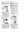
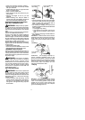
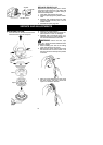
1. Loosen the coupler by turning the knob
counterclockwise.
Attachment
Coupler
Knob
LOOSEN
TIGHTEN
2. Press and hold the locking/release button.
Locking/Release
Button
Coupler
Upper Shaft
Attachment
3. Whilesecurelyholdingtheengineandup-
per shaft, pull theattachment straight out
of the coupler.
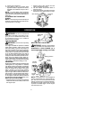
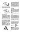
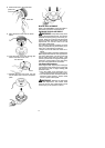
INSTALLING OPTIONAL ATTACH-
MENTS
1. Remove the shaft cap from the attach-
ment (if present).
2. Position locking/release button ofattach-
ment into guide recess of coupler.
3. Push theattachment intothecoupleruntil
the locking/release button snaps into the
primary hole.
4. Beforeusing theunit,tightenthe knobse-
curely by turning clockwise.
Coupler
Primary Hole
Upper
Shaft
Locking/
Release
Button
Attachment
Guide Recess
WARNING: M ake sure the locking/
release button is locked in the primary hole
andtheknob issecurely tightenedbeforeop-
erating the unit. All attachme nts are d esig ne d
to be u sed in the primary hole unless otherwise
stated in the applicable attachment instruction
manual. Usingthe w ronghole couldlead toseri-
ous i njury or da mage to the unit.
Locking/Release
Button in Primary Hole
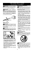
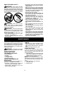
OPERATING POSITION
A
L
W
A
Y
SWE
A
R:
Hearing
protection
Eye protection
Heavy,
long pants
Boots
Cut from your left to your right.
Sa
f
ety helmet
When operating unit ,clip shoulder strap ont o
clamp, stand as shown and check for thefol-
lowing: