


56
Installation & Operation Manual
7 Operating information
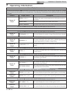
Status Display Screens (cont’d)
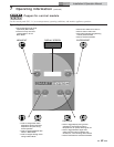
By using the Previous/Next (, ) arrow keys on the SMART SYSTEM display panel, you can navigate through the 11 display
screens. Each screen will contain two (2) viewable items. The following is a description of the individual items and what they
can display:
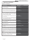
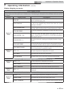
Screen # Display shows: Description
Screen #3
Line 2
SYSRTN: ***F (***)
The system return sensor acts as the control sensor. The control
will display the system return temperature as well as the set point in
parenthesis.
SYSRTN: OPEN The control does not detect the system return sensor.
SYSRTN: SHORTED The system return sensor wires or the sensor itself has become shorted.
Press the Next arrow key on the SMART SYSTEM display to access Screen #4.
N/A
Press the Next arrow key on the SMART SYSTEM display to access Screen #5.
Screen #5
Line 2
STG DEMAND: **** The control displays the number of stages firing, based upon demand.
Press the Next arrow key on the SMART SYSTEM display to access Screen #6.
Screen #6
Line 1
FAN SPEED: ***
The control will display either OFF, LOW, or HIGH depending upon
fan speed requirements of number of stages firing.
Screen #6
Line 2
0 – 10V RATE: **.*V
The control will display 0 to 10 volts based upon fan speed and unit
capacity.
Press the Next arrow key on the SMART SYSTEM display to access Screen #7.
Screen #7
Line 1
PH CFH: ***
The control will display either ON or OFF based upon a demand (call
for heat) for heat.
Press the Next arrow key on the SMART SYSTEM display to access Screen #8.
Screen #8
Line 1
SYS PUMP: ***
The control will display either ON or OFF based upon system pump
requirements upon demand.
Press the Next arrow key on the SMART SYSTEM display to access Screen #9.
Screen #9
Line 1
UNIT PUMP: ***
The control will display either ON or OFF based upon unit pump
requirements upon demand.
UNIT PUMP: DELAY
The control will display delay in unit pump operation after the heat
requirements have been satisfied.
Press the Next arrow key on the SMART SYSTEM display to access Screen #10.
Screen #10
Line 1
FLM SIG – A: **.* µA The control displays the igniter flame signal of igniter A in microamps.
Screen #10
Line 2
FLM SIG – B: **.* µA The control displays the igniter flame signal of igniter B in microamps.
Press the Next arrow key on the SMART SYSTEM display to access Screen #11.
Screen #11
Line 1
IGN * AMPS: *.* A The control displays the current of either igniter A or B.
Screen #11
Line 2
MIX VAL POS: ** % The control displays the mixing valve percentage open to the system.