


39
4 Water connections (continued)
Installation & Operation Manual
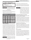
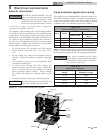
INSTALLED VIEW
END CAP
(JKD6653)
PLASTIC
ACTUATOR
COVER
VALVE COVER
(JKD6652)
END CAP
(JKD6654)
EXPLODED VIEW
*
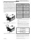
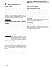
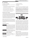
*NOTE: Refer to the numbers
located next to the terminals
when making wiring connections.
R
BK
O
BL
FIELD CONNECTIONS
TO TERMINAL #5
TO TERMINAL #6
TO TERMINAL #7
TO TERMINAL #19
LOW VOLTAGE BOARD
FACTORY CONNECTIONS
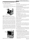
Manual operation of the 3-way automatic
bypass valve actuator
To manually operate the 3-way automatic bypass valve actuator:
1. Power must be removed from the unit.
2. Once power is removed, the de-clutch button located
on the side of the valve actuator body can be pressed.
Failure to remove power from
the actuator prior to attempting
to manually operate the valve can
result in irreparable damage to the
actuator mechanism.
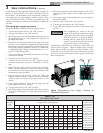
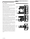
Figure 4-9_3 Way Valve Cover
Figure 4-8_3 Way Valve Cover Connection Diagram
Note: The actuator handle is not used when the outdoor cover is
installed. The handle is attached to the underside of the actuator
for storage.
CAUTION
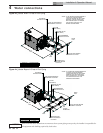
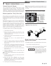
Outdoor operation: 3-way valve cover
If the pool heater is to be installed outdoors, the 3-way valve must
be protected from the elements. A cover for the 3-way valve is
included with the outdoor vent kits for all models (see Table 2F
on page 30).
Automatic bypass valve cover installation:
The pump supplied on the pool heater bypass has a sealed motor
suitable for outdoor installations. When installing the 3-way
automatic bypass valve outdoors, an outdoor valve cover is
required. An outdoor valve cover is supplied with an optional
outdoor vent kit (see Table-2D, page 25 of this manual).
To install the outdoor valve cover, follow the steps below:
1. Turn off power to the unit.
2. Remove the plastic actuator cover from the 3-way
automatic bypass valve by loosening the screw above the
conduit fitting (FIG. 4-9).
3. Grasp the cover on the screw side and lift the cover up and
away from the valve.
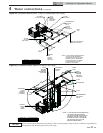
4. Disconnect the wires at the terminal block (if
connected).
5. Unscrew the plastic conduit cap from the conduit fitting
(FIG. 4-9) and pull the plastic conduit hose and wires
from the valve.
6. Feed the plastic conduit hose through the opening of the
valve cover end cap (JKD6654) (see FIG. 4-9) and slide
the end cap approximately one foot up the conduit.
7. Reconnect the wires to the 3-way valve circuit board as
shown in FIG. 4-8.
8. Feed the conduit hose into the conduit fitting and
reinstall the conduit cap.
Note: If the wing nut underneath the valve actuator body is
loose, retighten.
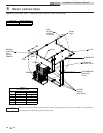
9. Reinstall the plastic actuator cover and secure with the
screw loosened in Step 2.
10. Place the valve cover (JKD6652) over the 3-way
automatic bypass valve. Install the end caps (JKD6653
and JKD6654) using the four screws provided in the kit
(BLT7901) as shown in FIG. 4-9.
11. Turn the power on to the unit and resume operation.
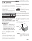
Pumped Automatic Bypass
This is a high efficiency pool heater which requires a special
pumped bypass for proper operation. The bypass assembly
supplied with the pool heater includes a pump and a 3-way
mixing valve. All piping to connect the filter system to the pool
heater is made directly to the bypass piping on the pool heater.