


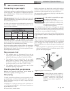
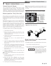


Heat exchanger
This is a highly sophisticated heat exchanger, designed to carry
water in such a way that it generates a scouring action which
keeps all interior surfaces free from build-up of impurities.
The straight-line, two pass design of the tubes sends water into
the headers at a properly rated velocity. The configuration of
the headers, in turn, creates a high degree of turbulence which
is sufficient to keep all contaminants in suspension. This
“scouring action” provides greater cost savings for owners.
Tubes are always able to transfer heat at peak efficiency.
Every surface within this water containing section is of a
non-ferrous material, providing clear, clean, rust-free water.
Straight copper tubes-finned on the outside for maximum
heat transfer-coated cast iron one piece cored headers make up
an entirely rust-proof pool heater, provided water chemistry is
maintained per the Water Chemistry requirements on page 45
of this manual. A Cupro-Nickel heat exchanger is standard on
1802 - 2072 models. On all models, header inspection plugs
can be removed for field inspection and cleaning of copper
tubes. The entire heat exchanger may be easily removed from
the pool heater.
ƽ CAUTION
An appliance allowed to operate at return
temperatures below the specified minimum
setting may experience problems with
the operating controls, safety switches,
obstruction of the flue gas passages on the
heat exchanger, incomplete combustion
and possible flue gas spillage. Sustained
operation at lower than specified water
temperatures (140°F) may cause hazardous
conditions that may result in personal injury
or non-warrantable damage to the appliance.
35
4 Water connections (continued)
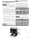
Initial set-up of maximum water flow
On initial start-up of the Copper-Fin
2
pool heater, the maximum
water flow to the heat exchanger must be checked and manually
limited with a valve or bypass before normal operation begins.
Installation & Operation Manual
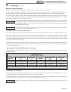
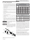
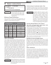
TABLE-4B
Minimum Pump Performance and Temperature Rise
Models GPM Ft.Hd. Temperature Rise
502 55 10 15.5°F
652 55 10 20.3°F
752 55 10 23.2°F
992 90 15 18.7°F
1262 90 15 23.8°F
1442 90 15 27.2°F
1802 115 18 26.6°F
2072 115 18 30.6°F
Minimum Pump Performance
Pump performance is based on providing adequate flow and
temperature rise to prevent scale accumulation in the heat
exchanger. See Water Chemistry on page 45.
ƽ WARNING
Should overheating occur or the gas supply
fail to shut off, do not turn off or disconnect
the electrical supply to the pump. Instead,
shut off the gas supply at a location external
to the pool heater.
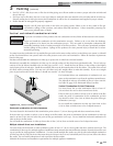
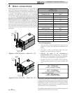
Auxiliary Mixed Water Limit Control
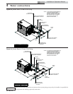
Pool return and pool supply (mixed water limit)
sensors (reference FIG. 4-3, page 36):
Ensure pool return and pool supply (mixed water limit) sensors
are both installed in the system piping. The return sensor should
be installed in the upstream of the feed water to the pool heater.
The supply sensor limits the temperature of the water going back
to the pool (factory adjusted to < 110°F). The supply sensor may
be installed in the filtration system piping, be sure to keep it at
least three (3) feet downstream from the point where the heated
water from the pool heater is being added to the filtration system.
Note: In order to accurately sense water temperatures, both
sensors need to be in the actual water flow.
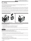
Installation of return and supply sensors:
Both pool sensors are immersion type sensors with 1/4" NPT
threads and may be installed directly into the system piping
by drilling 7/16" pilot holes and tapping them with a 1/4" NPT
tapered tap. Apply a small amount of high quality RTV silicone
sealant to the threads to prevent leaks and install the sensors into
the threaded openings in the PVC pipe. Over-tightening can
damage the parts and/or strip the threads cut into the plastic
pipe.
Sensor connections:
The sensors are connected to the pool heater from the factory.
The return sensor is a two-wire sensor and the supply sensor is a
four-wire sensor. Disconnects are provided for each sensor. If
disconnected to facilitate installation, re-connection is necessary
after installation. If sensors must be located further than
allowed by the cables provided, any extension cabling must be of
equivalent type and wire gauge (see Table 5B on page 41 of this
manual for recommended gauges). IMPORTANT: If the unit
is to be installed outdoors, weatherproof connections must be
provided over all sensor connections.
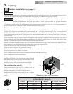
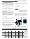
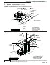
6 - 90° elbows 2 - ball valves
2 - unions ..................................................................
1 - cold water tee
Not more than 45 feet of straight pipe.
NOTICE
For every elbow and tee in excess
of those shown above, deduct 5 feet
from the maximum allowable straight
pipe in the pool heater to the system
circulating loop.