


41
5 Electrical connections
Installation & Operation Manual
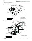
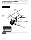
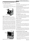
3-way automatic bypass valve wiring
If the piping loop was disassembled for shipping or needs to be
fitted with an outdoor enclosure, connection or disconnection
of the 3-way automatic bypass valve will be required. Wiring
connections should be made to the appropriately numbered
terminals on the 3-way automatic bypass valve as follows:
Note: Orientation of the valve connections may vary from what
is shown. Care should be taken to ensure wires are connected to
the appropriate terminals, see FIG. 4-8 on page 39 of this manual.
NOTICE
DO NOT block access to the electrical cover
plate when installing electrical conduit.
ƽ WARNING
Power must be removed and the clutch
button must be depressed before attempting
to manually operate the valve, or damage to
the 3-way valve may occur.
TABLE-5B
Remote Wire Connection
Wire
Gauge
Maximum
Allowable Length
12 GA 100 ft.
14 GA 75 ft.
16 GA 50 ft.
18 GA 30 ft.
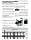
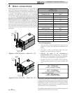
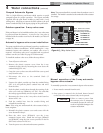
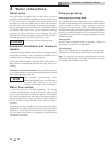
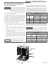
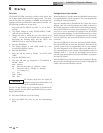
Figure 5-1_Control Panel Component Location
TRANSFORMER RELAY
MAIN CONTROL
BOARD
WIRE HARNESS
CONNECTIONS
BREAKER
LOCATION
OPTIONAL
AUXILIARY
HIGH LIMIT
LOCATION
LWCO/SWITCH
LOCATION
ON/OFF
SWITCH
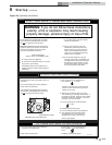
ELECTRICAL SHOCK HAZARD – For your
safety, turn off electrical power supply before
making any electrical connections to avoid
possible electric shock hazard. Failure to do
so can cause severe personal injury or death.
ƽ WARNING
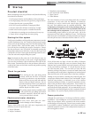
General information
A 120 VAC, 15 Amp, 1 ph, 60 Hz circuit is required for
operation of the appliance controls.
The appliance, when installed, must be electrically grounded
in accordance with the requirements of the authority having
jurisdiction or in the absence of such requirements, with the
latest edition of the National Electrical Code ANSI/NFPA No.
70. When the unit is installed in Canada, it must conform to
the CAE C22.1, Canadian Electrical Code, Part I and/or local
Electrical Codes. Multiple units connected in a Cascade must
be grounded to the same ground connection.
1. All wiring between the appliance and field installed
devices shall be made with type T wire [63°F (35°C)
rise].
2. All line voltage wire exterior to the appliance must be
enclosed in approved conduit or approved metal clad
cable.
3. The circulating pump must run continuously when
the appliance is being fired.
4. To avoid serious damage, DO NOT energize the
appliance until the system is full of water. Ensure that
all air is removed from the heat exchanger and piping
before beginning initial operation. Serious damage
may result if the appliance is operated without proper
flow.
5. Provide the appliance with proper overload protection.
TABLE-5A
3-Way Automatic Bypass Valve Wiring
Wire Color
FIELD FACTORY
3-Way Valve
Low Voltage
Board
1 Blue Terminal #1 Terminal #19
2 Orange Terminal #2 Terminal #7
3 Black Terminal #3 Terminal #6
4 Red Terminal #4 Terminal #5