


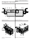
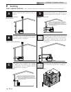
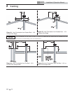

Vent system options: (Note: Installations shown below are representative, actual installations may vary from those shown.)
Installation & Operation Manual
14
2 Venting
A
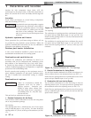
This option uses a vertical rooftop flue termination
with air supplied from the equipment room - see
page 16.
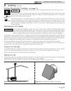
This option uses a powered vent assembly to
exhaust the flue products out a sidewall with air
supplied by a pipe from the sidewall - see page 25.
B
This option uses a vertical conventional vent for
flue products with air supplied by a pipe from the
sidewall or rooftop - see page 19.
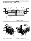
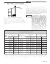
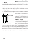
E
This option uses a sealed AL29-4C flue and a
separate combustion air pipe to the outdoors.
This system terminates both the flue and
combustion air inlet in the same pressure zone
- see page 26.
C
This option uses a powered vent assembly
to exhaust the flue products out a sidewall
vent termination with air supplied from the
equipment room - see page 22.
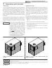
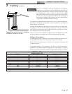
This option uses the installation of a special air
inlet / vent cap on top of the unit - see page 30.
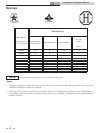
NOTE: CAT I B-VENT MATERIALS MAY BE USED WHEN THE
POWERED VENT IS CONNECTED DIRECTLY TO THE OUTSIDE
VENT CAP. IF THE POWERED VENT IS NOT CONNECTED
DIRECTLY TO THE OUTSIDE VENT CAP, THEN CAT IV - AL29-4C
VENT MATERIALS MUST BE USED FROM THE POWERED VENT
TO THE OUTSIDE VENT CAP.
12"
MIN
3'
MIN
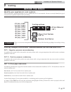
NOTE: CAT I B-VENT MATERIALS MAY BE USED WHEN THE
POWERED VENT IS CONNECTED DIRECTLY TO THE OUTSIDE
VENT CAP. IF THE POWERED VENT IS NOT CONNECTED
DIRECTLY TO THE OUTSIDE VENT CAP, THEN CAT IV - AL29-4C
VENT MATERIALS MUST BE USED FROM THE POWERED VENT
TO THE OUTSIDE VENT CAP.
12"
MIN
3'
3'
MIN
F
CONVENTIONAL NEGATIVE
DRAFT VENTING
VERTICAL DIRECTAIRE VENTING
SIDEWALL VENTING
OUTDOOR VENTING
HORIZONTAL DIRECTAIRE
VENTING
D