


33
3 Gas connections (continued)
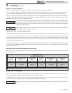
SUPPLY
INLET
PRESSURE
TAP
INLET
GAS
VALVE
CONTROL
KNOB
OUTLET
Installation & Operation Manual
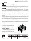
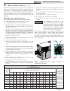
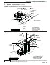
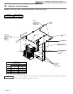
Figure 3-3_Measuring Gas Supply Pressure at
Combination Gas Valve
13. Remove the manometer and related fitting from the “inlet”
side of the gas valve, replace 1/8" hex plug in gas valve and
tighten.
14. Turn on gas supply at the manual valve, turn on L.P. gas at
the tank if required.
15. Turn the power switch to the “ON” position.
16. Turn the gas valve knob to the “ON” position.
17. Set the electronic temperature control or thermostat to call
for heat.
Combination gas valve/regulators equipped with integral vent
limiters are not required to have vent or relief lines piped to
the outdoors. The termination of the vent limited opening on
the combination gas valve/regulator complies with the safety
code requirements of CSD-1, CF-190(a) as shipped from the
appliance manufacturer without the installation of additional
vent lines.
Checking gas supply pressure
Use the following procedure to check gas supply pressure.
1. Turn the main power switch to the “OFF” position.
2. Turn gas valve knobs to the “OFF” position.
3. Shut off gas supply at the field-installed manual gas cock in
the gas piping to the unit. If fuel supply is L.P. gas, shut off
gas supply at the tank.
4. Remove the 1/8" hex plug, located on the “inlet” side of the
gas valve. You may also use a tapping on the field-installed
main manual gas cock or gas piping. Install a fitting in the
inlet pressure tapping suitable to connect to a manometer
or magnehelic gauge. Range of scale should be 14" w.c. or
greater to check inlet pressure.
5. Turn on gas supply at the manual gas cock, turn on L.P. gas
at the tank if required.
6. Turn the power switch to the “ON” position.
7. Turn the gas valve knobs to the “ON” position. Set the
electronic temperature control or thermostat to call for
heat.
8. Observe the gas supply pressure as all burners are firing.
Ensure that inlet pressure is within the specified range.
See Connecting To Gas Supply, page 31 for minimum and
maximum gas supply pressures.
9. If gas pressure is out of range, contact gas utility, gas
supplier, qualified installer or service agency to determine
necessary steps to provide proper gas pressure to the
control.
10. If gas supply pressure is within normal range, turn the
power switch to the “OFF” position.
11. Turn gas valve knobs to the “OFF” position.
12. Shut off gas supply at the manual gas cock in the gas piping
to the unit. If fuel supply is L.P. gas, shut off gas supply at
the tank.
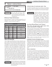
TABLE - 3D
GAS PIPING SIZE CHART
Nominal
Iron Pipe
Size
Inches
Length of Pipe in Straight Feet
Maximum
Capacity of Pipe
in Thousands of
Btu/hr per hour
for gas pressures
of 14 Inches
Water Column
(0.5 PSIG) or less
and a pressure
drop of 0.5 Inch
Water Column
(Based on NAT
GAS, 1025 Btu/hr
per Cubic Foot
of Gas and 0.60
Specific Gravity)
10 20 30 40 50 60 70 80 90 100 125 150 175 200
3/4 369 256 205 174 155 141 128 121 113 106 95 86 79 74
1 697 477 384 328 292 267 246 256 210 200 179 164 149 138
1 1/4 1,400 974 789 677 595 543 502 472 441 410 369 333 308 287
1 1/2 2,150 1,500 1,210 1,020 923 830 769 707 666 636 564 513 472 441
2 4,100 2,820 2,260 1,950 1,720 1,560 1,440 1,330 1,250 1,180 1,100 974 871 820
2 1/2 6,460 4,460 3,610 3,100 2,720 2,460 2,310 2,100 2,000 1,900 1,700 1,540 1,400 1,300
3 11,200 7,900 6,400 5,400 4,870 4,410 4,000 3,800 3,540 3,300 3,000 2,720 2,500 2,340
4 23,500 16,100 13,100 11,100 10,000 9,000 8,300 7,690 7,380 6,870 6,150 5,640 5,130 4,720
ƽ WARNING
After completing any testing on the gas
system, leak test all gas connections. Apply
a soap/water solution to all gas connections
while main burners are operating. Bubbles
forming indicate a leak. Repair all leaks at
once. Do not operate this unit with a leak in
the gas train, valves or related piping.
Check burner performance by cycling the system while you
observe burner response. Burners should ignite promptly.
Flame pattern should be stable, see Burner Flames in the
Copper-fin
2
Service Manual. Turn system off and allow burners
to cool, then cycle burners again to ensure proper ignition and
flame characteristics.