


42
5 Electrical connections
Installation & Operation Manual
Installation must comply with:
1. National Electrical Code and any other national, state,
provincial, local codes, or regulations.
2. In Canada, CSA C22.1 Canadian Electrical Code Part 1, and
any local codes.
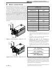
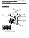
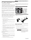
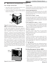
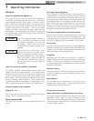
Pool heater operating control module
The operating control for the appliance is the SMART
SYSTEM control module. It is located on the inside of the
control panel, behind the front access door. Access to adjust
the temperature set point and other user adjustable points
is made through the Operator Interface located on the front
access door.
The exact temperature set point is based on the system’s
requirements. Set the control set point(s) to the desired
operating water temperature.
The maximum temperature set point that can be programmed
into the control module from the Operator Interface on a
pool heater is 105°F (40.5°C). The manual reset high limit
control for a pool heater is adjustable up to a fixed maximum
setting of 200°F (93°C).
TABLE - 5C
AMP DRAW DATA
Model Controls Blower
Pump
FLA*
Approximate Total
Amps @ 120 VAC
502 3.6 2.7 5.8 12.1
652 5.4 3.4 5.8 14.6
752 5.4 3.4 5.8 14.6
992 7.3 3.2 7.4 17.9
1262 7.3 3.2 7.4 17.9
1442 7.3 6.7 7.4 21.4
1802 7.3 6.7 8.8 22.8
2072 7.3 6.7 8.8 22.8
*With standard factory supplied pump.
ELECTRICAL SHOCK HAZARD – For your
safety, turn off electrical power supply before
making any electrical connections to avoid
possible electric shock hazard. Failure to do
so can cause severe personal injury or death.
Wiring must be N.E.C. Class 1.
If original wiring as supplied with the pool
heater must be replaced, use only type 105°C
wire or equivalent.
Pool heater must be electrically grounded as
required by National Electrical Code ANSI/
NFPA 70 – latest edition.
Label all wires prior to disconnection when
servicing controls. Wiring errors can cause
improper and dangerous operation.
ƽ WARNING
NOTICE
ƽ CAUTION
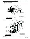
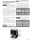
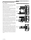
Line voltage connections
1. Connect 120 VAC power wiring to the line voltage
terminal strip in the junction box, as shown in FIG. 5-2.
2. Provide and install a fused disconnect or service switch
(15 AMP recommended) as required by the code (see
FIG. 5-2).
3. To activate the unit, wire as shown in FIG. 5-2. If the
motor is larger than 1 HP, you must install a contactor.
4. When connecting power to units which are to be
cascaded, each unit must be connected to the same ground
connection.
LN
120V
SUPPLY
UNIT
PUMP
1 HP MAX
LNG LNG
UNIT
SUPPLY
UNIT PUMP
SUPPLY
UNIT
PUMP
CHASSIS
GROUND
GROUND
SPLICE
D
I
S
C
O
N
N
E
C
T
D
I
S
C
O
N
N
E
C
T
Figure 5-2_Line Voltage Field Wiring Connections