


7
Knobs previously installed.
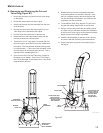
E. Changing the direction of the Discharge
Chute (Figure #4)
1. Loosen the Knobs (38524) by hand and, if needed, the
Nuts (64229-03) with a 1/2” wrench.
2. Rotate the Discharge Chute to the desired position.
3. Retighten the Knobs by hand and the Nuts, if
loosened, with the 1/2” wrench.
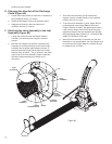
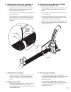
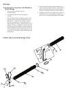
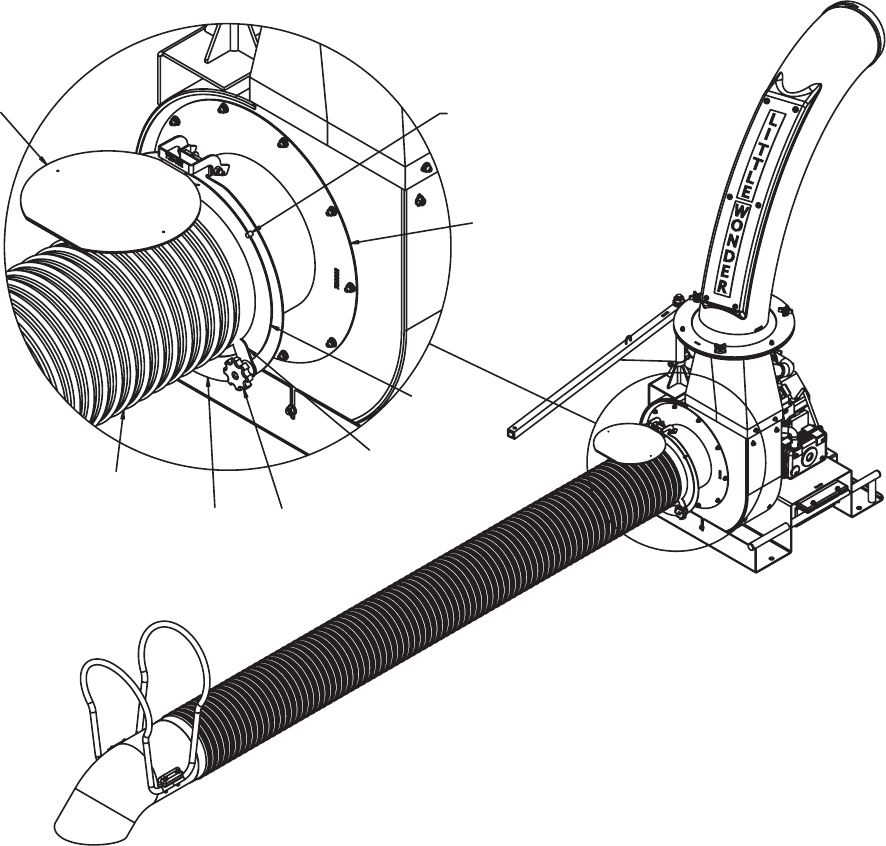
F. Attaching the Hose Assembly to the Inlet
Assembly (Figure #5)
1. Loosen the knob and rotate the Flapper Retainer
(720258.10) to allow the Inlet Flapper to be lifted
upward.
2. With the Inlet Flapper held upward, install the Hose
Assembly by inserting the flange of the Hose Flange
Assembly into the space (gap) between the face of
the Inlet Assembly Flange and the back face Flange
Retainer Plate as shown. The pin located in the upper
right corner of the Inlet Assembly Flange will prevent
the Hose Flange Assembly from sliding out of
this pocket.
3. Since the Hose Assembly may be rotated 360
degrees, orient the Intake Nozzle to your preferred
position and lock it in place.
4. To lock the Hose Assembly in place, tighten the two
knobs attached to the Flange Retainer Plate and
Flapper Retainer as shown. By tightening the knobs,
it will push the flange of the Hose Flange Assembly
against the flange of the Inlet Assembly and activate
the Safety Switch Plate (720234.17). THIS MUST BE
DONE TO OPERATE THIS UNIT.
5. When the Hose assembly is removed from the Inlet
Assembly for unit transportation, the Inlet Flapper must
be closed and the Flapper Retainer (720258.10) must
be rotated to lock it in place.
FIGURE #5
INLET
FLAPPER
INLET
ASSEMBLY
PIN
KNOB
FLAPPER
RETAINER
HOSE
FLANGE
ASSEMBLY
HOSE
ASSEMBLY
FLANGE
RETAINER PLATE
Figure #5