


9
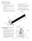
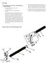
L. Discharge Extension Kit Assembly
Instructions
Contents Included in Kit:
1. Discharge Extension Hose (720436)
2. Hose Clamp (720388)
Tools Needed:
1. 9/16” Box Wrench or Socket Wrench w/ 9/16” Socket
2. Socket Wrench w/ 3/8” Socket or Flat Head
Screw Driver
3. Utility Knife (if required)
4. Heavy Duty Wire Cutters (if required)
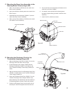
Disassembly and Assembly Instructions:
1. Turn off the TruckLoader and disconnect both of the
spark plug wires from the engine.
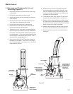
2. Disassemble the TruckLoader Discharge Flapper by
removing the knob, (2) nuts, (2) washers, and (3) bolts.
3. Remove the Discharge Flapper from the
Discharge Nozzle.
4. Slide the Discharge Extension Hose over the end of
the Discharge Nozzle where the Flapper has been
removed. Make sure the Hose has overlapped the
Discharge Nozzle by at least 6 inches.
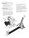
5. Secure the attachment of the Discharge Extension
Hose to the Discharge Nozzle with the supplied Hose
Clamp. When installing the Hose Clamp, make sure
it is positioned between the 1st and 2nd coil of the
Discharge Extension Hose. Once in position, tighten
the clamp to ensure a firm connection of the two parts.
6. Insert the opposite end of the Discharge Extension
Hose into the receiver box on your truck. In the event
the Hose is too long for your application, you can
choose to cut it to a shorter length. If you shorten the
length of this hose, make sure enough hose is left to
properly install and secure it into the truck.
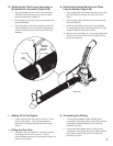
7. Once the Hose is properly fit into your truck, secure it
in place with a rope, bungee cord, etc., as required to
secure it in place.
8. Make sure the Discharge Nozzle and Discharge
Extension Hose is positioned to ensure a straight flow
from the TruckLoader into your receiver box.
9. Once everything has been properly positioned and
secured, reconnect both spark plug wires on your engine.
Maintenance and Operation:
1. Be sure to check the positioning and all connections of
your TruckLoader before starting.
2. To increase the life of your Discharge Extension
Hose, periodically rotate the position of this hose.
This can be accomplished by repeating the Assembly
instructions specified above.
Operation:
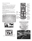
A. Starting the Engine
1. Check the oil level. Add oil if necessary.
2. Check the air cleaner for dirty, loose, or damaged
parts. Clean or replace parts as necessary.
3. Check the air intake and cooling area for dirt or debris
and clean as necessary.
4. Move the choke control lever to the “choke” position.
5. Move the throttle control lever to the middle position.
6. Turn the ignition key clockwise to start the engine. As
soon as the engine starts, release the key.
7. After letting the engine warm up, slowly move the
choke lever to the “open” run position.
8. See the engine manual for additional information
on starting.
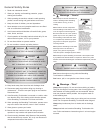
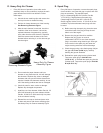
B. Vacuuming
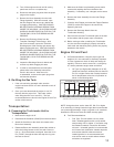
1. This machine has been designed for two methods of
vacuuming debris.
• WiththehandlesoftheIntakeNozzleinthe
operator’s hands, move the Nozzle back and
forth in a sweeping motion over the debris.
• RotatetheHoseAssembly90degreesatthe
Inlet to allow the Intake Nozzle to lay sideways
on the ground. By placing the Nozzle in this
position, debris can be raked into the Nozzle by
the operator.
2. While large amounts of debris can be vacuumed
quickly with this machine, caution must be taken to
avoid blocking the airflow into the Nozzle.
3. To increase the life of your Hose, periodically rotate
the Intake Nozzle with respect to the Hose. This will
allow the hose to wear more evenly.
C. Stopping the Engine
1. Move the throttle control lever to the “turtle”
(slow) position.
2. Turn the key to the “off” position.
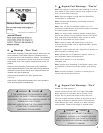
D. Debris Blockage
1. If a decrease in suction is experienced, there may be a
debris blockage in the hose. To remove this blockage,
simply grab the handles of the Intake Nozzle and
stretch the hose out into a straight line with respect to
the Inlet of the unit while the engine is at full throttle.
2. In the event the suction of the hose remains decreased
after completing step #1, there may be a blockage in
the housing. In order to inspect the unit for blockages,
complete the following steps: