


5
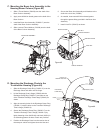
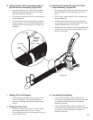
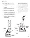
B. Mounting the Shredding TruckLoader
Frame (Figure #2)
1. There are four holes in the TruckLoader frame
deck through which the unit can be secured to an
appropriate mounting surface. For your convenience,
(4) Bolts (64123-234) and (4) Nuts (64268-07) have
been provided for the installation.
2. For the purpose of lifting your unit, two options have
been provided for you. The first option is a lifting
lug found near the engine muffler mounted on the
backside of the Housing Assembly. This lug has
been designed to hold a maximum of 500 pounds.
The second option is the lifting bars, which are
incorporated in the frame and found on either side
of the Housing Assembly.
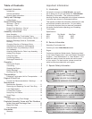
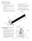
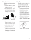
Assembly Instructions:
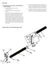
A. Hose Assembly (Figure #1)
1. Remove the Hose from the box.
2. With the assistance of a second person, hold the hose
at both ends and stretch it out as far as possible.
This will maximize the hose length and open the
internal diameter.
3. Insert the Hose Flange Assembly into one of the open
ends as shown.
4. Using one of the Hose Clamps, secure the hose to the
Hose Flange Assembly by wrapping the clamp around
the hose portion covering the Hose Flange and tighten.
5. Insert the Intake Nozzle into the end of the hose
opposite the hose flange as shown.
6. Using the second Hose Clamp, secure the hose to the
Intake Nozzle by wrapping the clamp around the hose
portion covering the Intake Nozzle and tighten.
7. Install the Intake Nozzle Handle as shown.
8. To secure the Intake Nozzle Handle to the Intake
Nozzle, insert the (4) Bolts (64262-020) and (4) Nuts
(64229-03) that have been provided for the installation.
HOSE FLANGE
HOSE
ASSEMBLY
HOSE CLAMP
NUT
HANDLE
INTAKE NOZZLE
BOLT
INTAKE NOZZLE
HOSE CLAMP
FIGURE #1
Figure #1
Figure #2
FRAME DECK MOUNTING HOLES
LIFTING LUG
FRAME
LIFTING BARS