


26
Section 3: Adjustments
ZT60 & ZT72 Zero Turning Radius Mowers Riding Mowers Accu-Z
®
357-103M
8/26/08
Land Pride
Table of Contents
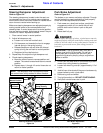
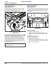
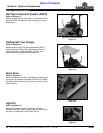
Refer to Figure 3-6 & Figure 3-7:
9. Check gap between actuator lever (#1) and hydraulic
motor (#2). The gap should be approximately
1/16" (.06").
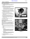
10. Adjust park brake if gap is greater than 1/8" (.12") or
if actuator lever (#1) touches hydraulic motor (#2):
a. Move left control lever to neutral.
b. Loosen jam nut (#3) and turn adjusting rod (#4)
counter clockwise two turns to increase the gap
and clockwise two turns to decrease the gap.
11. Move left control lever to park and recheck gap.
12. Repeat steps 10 and 11 until correct gap is achieved.
If correct gap cannot be achieved, see "Adjusting the
Park Brake Lever Arm" below.
13. Once gap is correct, tighten jam nut (#3).
14. Making certain both control levers are in park,
reinstall drive wheel and lug nuts. Do not torque lug
nuts at this time.
15. Jack mower up off the jack stand and remove jack
stand. Lower mower safely to the ground.
16. Tighten drive wheel lug nuts to the correct torque.
See “Additional Torque Values” on page 58 for
correct torque value.
17. Repeat steps 4 through 16 for the right side.
18. Turn ignition switch to off.
19. Remove wheel chocks.
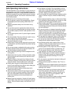
Adjusting the Park Brake Lever Arm
Refer to Figure 3-7:
The park brake lever arm should be adjusted only after
following instructions for “Park Brake Adjustment” on
page 25 and if you run out of threads on adjusting
rod (#4) while making adjustments in step 12 above, then
the park brake lever arm (#5) will need adjusting as
follows:
1. With both control levers in park, move the control
lever located on the same side as the park brake to
neutral.
2. Make adjustments to park brake lever arm (#5) as
follows:
a. Method #1:
Loosen round head square neck bolts (#6 & #7)
and adjust lever arm (#5) in the square slot to
provide additional take-up at adjusting rod (#4).
Tighten bolts (#6 & #7) to the correct torque.
b. Method #2:
Use method 2 only if method 1 does not work.
Remove bolt (#8) and reinstall in lower hole (#9).
Tighten bolt (#8) to the correct torque.
3. Place control lever in park.
4. Continue by following instructions beginning with
step 9 above.
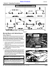
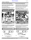
Park Brake Gap
Figure 3-6
Park Brake Adjustment
Figure 3-7
2
Measure gapbetween
lever arm (#1) and
hydraulic motor (#2).
24826
1
4
3
9
24827
8
6
5
7