18
Section 2: Operating Procedures
ZT60 & ZT72 Zero Turning Radius Mowers Riding Mowers Accu-Z
®
357-103M
8/26/08
Land Pride
Table of Contents
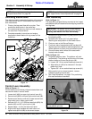
Moving Mower with Stalled Engine
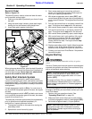
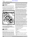
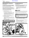
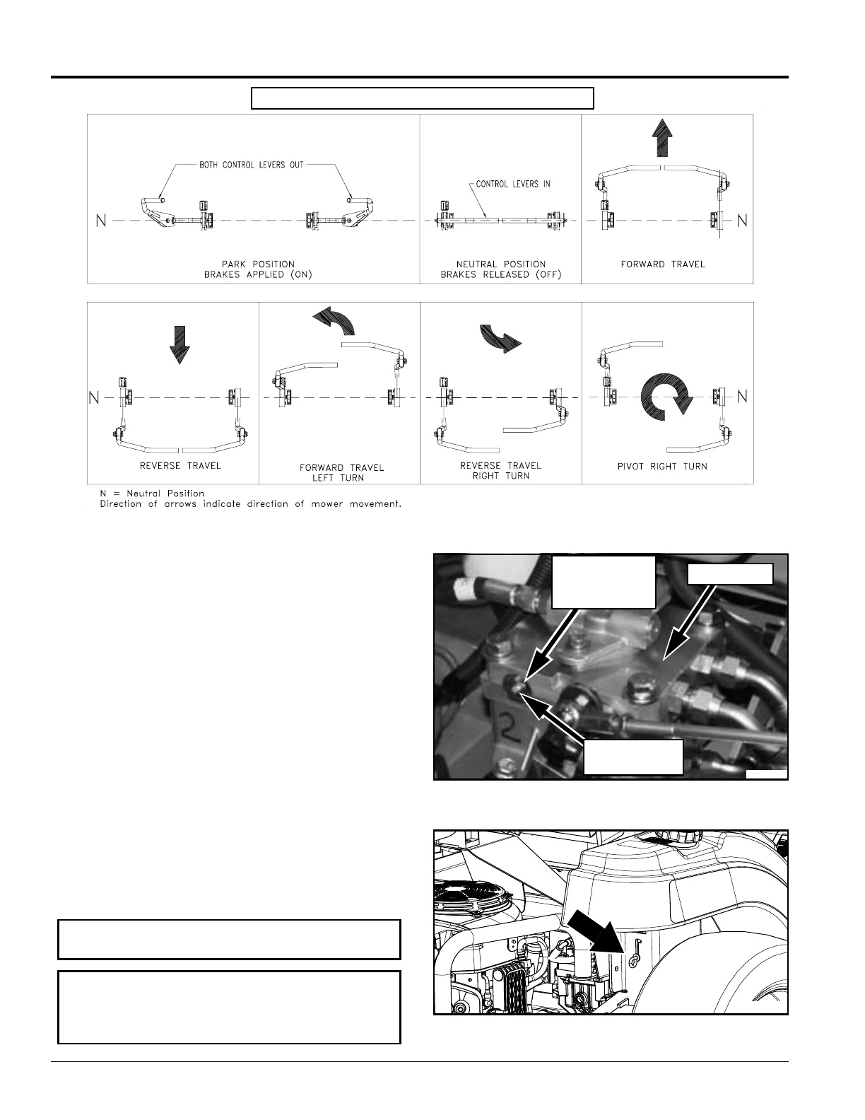
Refer to Figure 2-8:
Located under the seat are two hydro-drives. One on the
right side and one on the left side. Each hydro-drive is
equipped with a bypass valve for moving the mower
manually when the engine is inoperable. The bypass
valve is located to the inside near the top and is identified
as a hex stud. Before moving mower manually:
1. Loosen hex jam nuts with 17mm wrench and turn both
bypass valves with 8mm wrench counter clockwise
one-half of a turn.
2. If the mower has electrical power, turn ignition switch
to (ON) and position both control levers in neutral with
handles together to release park brakes.
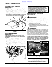
Refer to Figure 2-9:
3. If mower has lost electrical power, manually release
park brakes with release levers located at the rear
under the gas tanks. Raise levers and position them
into the notched slots. A pry bar leveraged over the
tires may be required to overcome the spring forces
required to set the park brakes.
.
IMPORTANT: Do not tow the machine. Move it by
hand or use a winch and load it on a trailer.
IMPORTANT: Following repairs and before
operating the mower, always make certain the two
bypass valves and two park brake release levers are
returned to their normal operating positions.
Bypass Valve (Left Side Shown)
Figure 2-8
Park Brake Release Lever (Right Side Shown)
Figure 2-9
23993
Bypass Valve
Hex Jam Nut
(17mm Wrench)
Hydro-Drive
Bypass Valve
(8mm Wrench)
23932
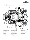
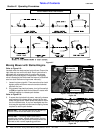
Figure 2-7
Front of Mower Faces This Direction
23923


