


10
Section 1: Assembly & Set-up
ZT60 & ZT72 Zero Turning Radius Mowers Riding Mowers Accu-Z
®
357-103M
8/26/08
Land Pride
Table of Contents
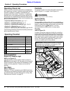
Section 1: Assembly & Set-up
Uncrating Instructions
The shipping crate is assembled together at the corners
with nails and the Accu-Z is secured to the crate floor
with metal bands.
1. First pry the top panel free with a pry bar. Then
remove the side panels in the same way.
2. Cut metal bands securing front and rear wheels to
the crate floor. Discard bands.
3. Complete assembly instructions and engine
preparations below before driving mower off the
crate floor.
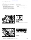
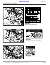
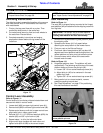
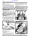
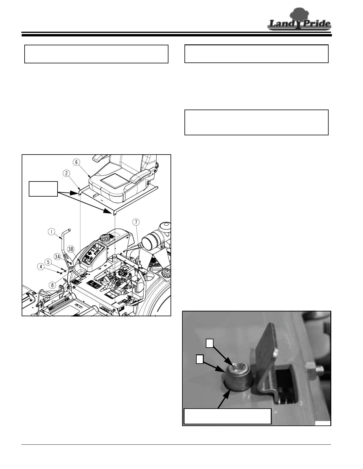
Control Lever & Seat Assembly (Standard Seat Shown)
Figure 1-1
Control Lever Assembly
Refer to Figure 1-1:
Control levers (#1) are factory shipped rotated down and
secured with bolts in control levers.
1. Loosen bolt (#3A) on upper right control lever (#1).
2. Remove bolt (#3B) from lower right control lever (#8).
3. Rotate control lever up until slot in upper control lever
aligns with hole in lower control lever.
4. Reinstall 3/8"-16 1 1/2" GR5 hex head bolt (#3B), flat
washer (#5) and 3/8" nylon lock nut (#4).
5. Repeat steps 1 to 4 for the left control lever.
6. Align control lever handles with each other and
tighten bolts (#3A & #3B) to the correct torque.
NOTE: For correct torque values, refer to
“Torque Values Chart” on page 58.
23940
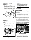
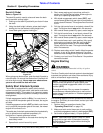
Platform
Tabs
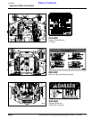
Seat Assembly
Refer to Figure 1-1:
The seat (#6) is shipped factory mounted to the hinged
seat platform (#2) and attached to the shipping crate with
four lag bolts.
1. Remove four lag bolts securing seat platform (#2) to
the shipping crate.
2. Spread control levers (#1) fully apart before
attaching the seat platform to the mower frame.
3. Pivot arm rest on the Deluxe Seat up.
4. Pivot back side of seat platform (#2) up about 45
degrees and Insert platform tabs through slots in the
mower platform and onto pins just below the slots.
5. Connect mower switch wires to the seat switch
located under the seat.
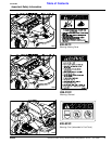
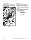
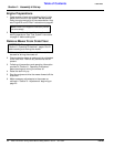
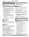
Refer to Figure 1-2:
6. Hinge seat platform down. The platform will latch
automatically. The following must be done if the seat
platform does not fit over the pilot pin (#2).
a. Loosen 3/8"-16 hex socket head cap screw (#1).
b. Adjust pilot pin (#2) to be centered in the seat
platform pin hole.
c. Tighten 3/8"-16 hex socket head cap screw (#1).
7. Being careful not to cut seat material, remove
protective packing around seat.
8. See "Seat Adjustment" on page 27 for positioning
this seat forward and rearward.
Seat latch Adjustment
Figure 1-2
NOTE: To make final control lever adjustments,
see "Upper Control Lever Adjustments" on page 27.
IMPORTANT: Be careful not to cut seat material
when removing protective packing around the seat.
Cutting seat material will void its warranty.
1
2
Pilot Pin (#2) (must be centered
in seat platform pin hole.
24828