


15
Section 2: Operating Procedures
8/26/08
ZT60 & ZT72 Zero Turning Radius Mowers Riding Mowers Accu-Z
®
357-103M
Land Pride
Table of Contents
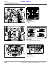
Choke
Refer to Figure 2-2 on page 14:
A cable is linked from engine to choke knob to choke the
engine during starting. When choke control knob is
down, the choke is off (engine running position). When
control knob is pulled up, the choke is on (engine starting
position). Shut choke off soon after engine has started.
Blade Engagement Switch
Refer to Figure 2-2 on page 14:
The blade engagement switch engages the deck blades.
Pull switch up to engage blades and push switch down to
disengage blades.
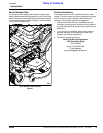
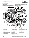
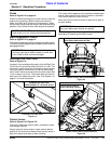
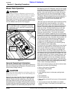
Left/Right Fuel Tank Valve
Refer to Figure 2-3:
Located in front and below the seat is the Left/Right Fuel
Tank Valve for controlling which fuel tank is in use. The
valve lever must be over one of the two arrows to supply
fuel to the engine. Arrows point to the fuel tank being
used. Switch valve from one tank to the other when tank
in use is about out of fuel. The mower does not have to
be turned off to make the switch. See “Fuel System” on
page 41 for more information.
Left/Right Fuel Tank Valve
Figure 2-3
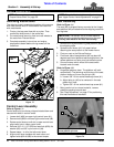
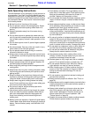
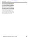
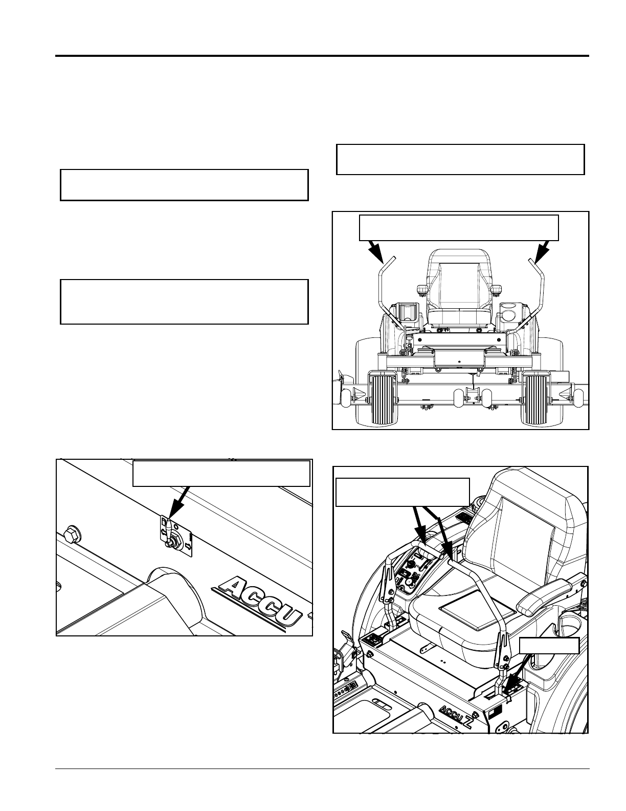
Control Levers
Refer to Figure 2-4 & Figure 2-5:
The control levers are used to steer, accelerate, brake
and change direction.
Always set both control levers in park position before
getting off the mower and always leave control levers in
park until seated and ready to start traveling.
IMPORTANT: DO NOT operate mower with the
choke pulled up or on. (engine starting position).
IMPORTANT: Never engage blades with engine
running at high rpm or when the deck is under load.
Clutch, belts or deck could be damaged.
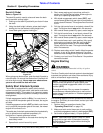
26698
Left/Right Fuel Tank Valve
Center Position “O” as Shown is OFF
Pull control levers together at the handles to release park
brakes. Move control levers either forward or rearward
from neutral position to start moving.
Move the control levers to neutral to stop and to park to
set park brakes.
See “Driving the Mower” on page 17 for a detailed
description of operating the control levers.
.
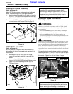
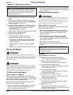
Control Levers (Set in Park Position)
Figure 2-4
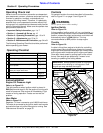
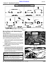
Control Levers (Set In Neutral Position)
Figure 2-5
IMPORTANT: Both control lever must be spread
fully apart before park brakes are applied.
23924
Both Control Lever Must Be Spread Fully
Apart Before Park Brakes Are Set.
23930
Control Levers Placed In
Neutral Operating Position
Neutral Slot