


24
RCB6010 & RCB6015 (540 RPM) and RCMB6010 & RCMB6015 (1000 RPM) Rotary Cutters 318-263M 9/04/08
Land Pride
Section 4: Maintenance & Lubrication
Table of Contents
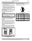
6. Tighten each of the 8 spring retainer nuts on the
clutch housing exactly 2 revolutions to restore clutch
to original setting pressure.
7. Allow clutch to cool to ambient temperature before
operating again. Clutch is now ready for use.
8. The clutch should be checked during the first hour of
cutting and periodically each week. An additional set
of scribe marks can be added to check for slippage.
See Figure 5-5 to adjust spring length.
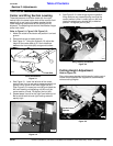
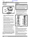
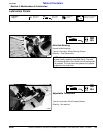
Clutch Disassembly, Inspection & Assembly
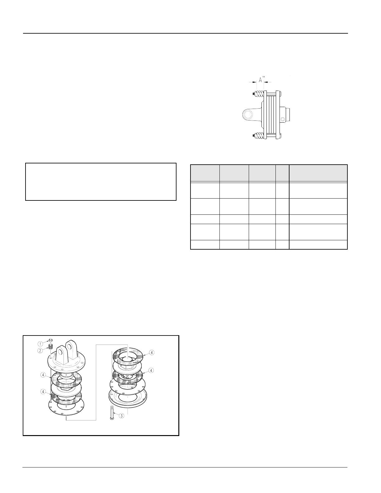
Refer to Figure 5-4:
If clutch run-in procedure above indicated that one or more
friction disks did not slip, then the clutch must be
disassembled to separate the friction disks.
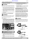
Disassembly
Disassembly of clutch is simply a matter of first removing
spring retainer nuts (#1), springs (#2) and bolts (#3) from
the assembly. Each friction disk (#4) must then be
separated from the metal surface adjacent to it.
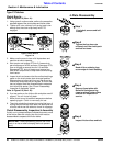
Inspection
Inspect all parts for excessive wear and condition. Clean
all parts that do not require replacement.The original
friction disk thickness is 1/8" (3.2mm) and should be
replaced if thickness falls below 3/64" (1.1mm). If
clutches have been slipped to the point of “smoking”, the
friction disks may be damaged and should be replaced.
Heat build-up may also affect the yoke joints.
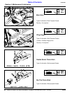
Assembly
Reassemble each friction disk (#4) next to the metal
plate it was separated from. Install bolts (#3) through the
end plates and intermediate plates as shown. Place
springs (#2) over the bolts and secure with nuts (#1).
Type A Clutch Disassembly
Figure 5-4
IMPORTANT: Not all Type A clutch components are
arranged as illustrated in Figure 5-4. Also some
have more components than others. Be sure to keep
track of order and orientation of your clutch
components during disassembly.
14714
IMPORTANT: Keep track of order and orientation of
your clutch components during disassembly
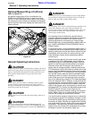
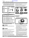
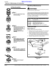
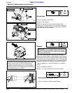
Refer to Figure 5-5 & Table Below:
Progressively tighten each spring retainer bolt until
correct spring height “A” is reached.
Type A Clutch Adjustment
Figure 5-5
Driveline
No.
Driveline
Location
PTO
Speed
Cat
No.
A (inches)
Spring Height
826-183C Center 540 4 1.15" (S/N 566919+)
1.12" (S/N 566918-)
826-184C Center 1000 4 1.09" (S/N 566919+)
1.02" (S/N 566918-)
826-478C Center 540/1000 5 1.32"
826-185C Wing 540/1000 4 1.175" (S/N 566919+)
1.14" (S/N 566918-)
826-481C Wing 540/1000 5 1.32"
24600