


12
RCB6010 & RCB6015 (540 RPM) and RCMB6010 & RCMB6015 (1000 RPM) Rotary Cutters 318-263M 9/04/08
Land Pride
Section 1: Preparation and Set-up
Table of Contents
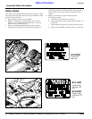
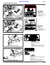
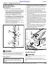
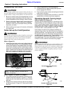
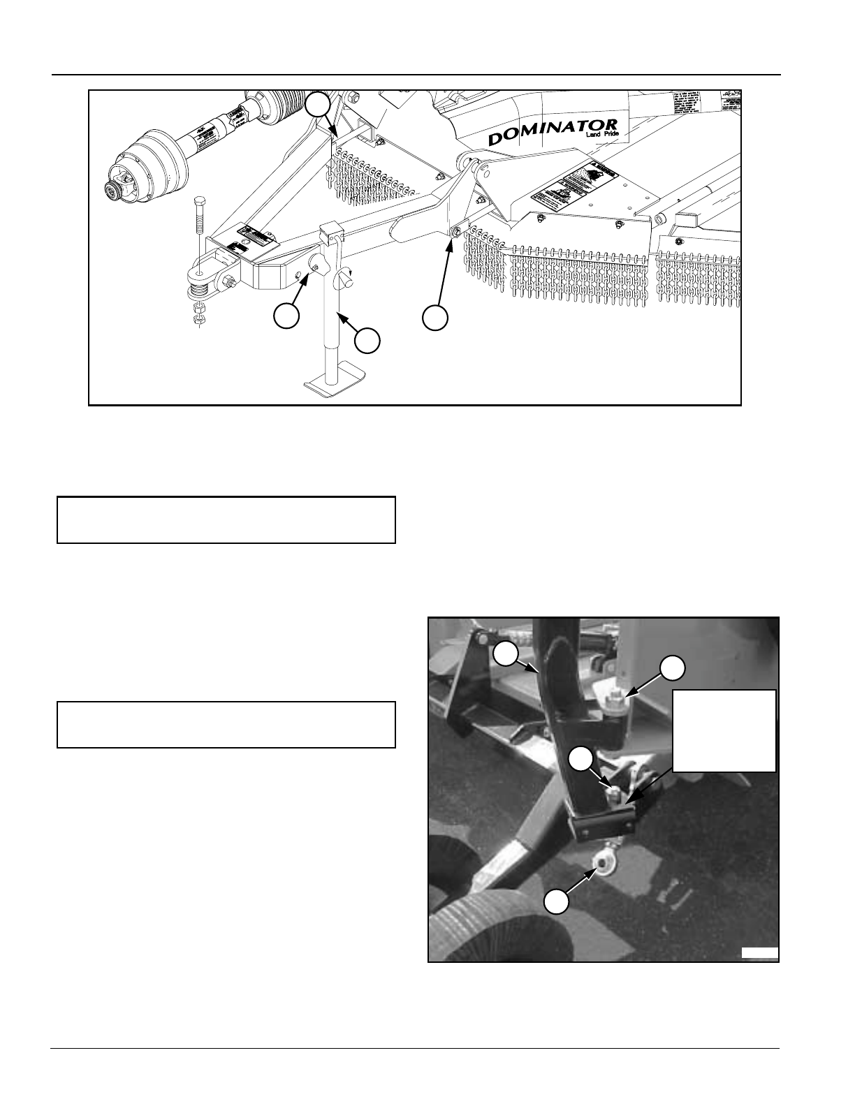
Hitch Assembly
Refer to Figure 1-2:
1. Install left and right leveling rods (#1) to the hitch
frame with 3/4” x 1 1/2” clevis pins, 3/4” flat washers,
and 1/8” x 1 1/4” cotter pins. Final adjustment should
be made when the cutter is attached to the tractor.
2. Install parking jack (#2) to the hitch frame and secure
with attached pin (#3). Adjust parking jack to
preferred drawbar height.
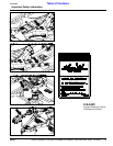
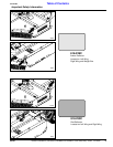
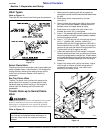
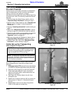
Wing Axle Assembly
Refer to Figure 1-3
Wing axle locknuts are tightened for shipping purposes.
1. Loosen lock nuts (#1) slightly and rotate wing axles
(#2) to install turnbuckles (#3).
2. Remove cap screws and locknuts (#4). Attach
turnbuckles (#3) to the wing axles with existing cap
screws and lock nuts (#4).
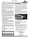
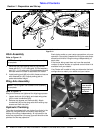
Hydraulic Plumbing
The cutter is equipped with one hydraulic cylinder in the
center for lifting the cutter and one on each wing for
folding of the wings independently. All cylinders on the
cutter are single action (one-way) type and should not be
plumbed for two-way operation.
NOTE: Do not tighten the hardware until assembly
is complete.
NOTE: Do not tighten the hardware until assembly
is complete.
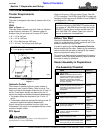
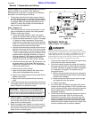
Each duplex outlet on your tractor can perform only one
operation. One outlet is needed for lifting the cutter and a
second and third for lifting the wings independently of
each other.
If the tractor being used does not have the required
number of duplex outlets, an optional control valve kit is
available from your dealer.
Your Dealer will be able to help you determine the best
configuration to match your needs and your tractor.
Wing Axle - Turnbuckle Assembly
Figure 1-3
23703a
4
3
2
1
Turnbuckle(#3)
to be secured
between this
flange and the
one below.
Hitch Assembly Illustration
Figure 1-2
1
1
3
2
23578