15
Section 1: Preparation and Set-up
9/04/08
RCB6010 & RCB6015 (540 RPM) and RCMB6010 & RCMB6015 (1000 RPM) Rotary Cutters 318-263M
Land Pride
Table of Contents
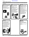
Always engage the PTO at low engine rpm to minimize
start-up torque on the driveline. See “Section 4:
Maintenance & Lubrication” on page 22 for a detailed
description of maintaining the driveline.
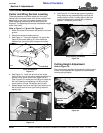
1. The driveline shaft from the tractor may be either a
constant velocity type or a conventional type. Attach
the 1 3/4-20 splined end to the input shaft of the divid-
er gearbox. Attach the opposite splined end to the
tractor PTO shaft. Skip to step 3 if driveline fits be-
tween tractor and implement.
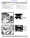
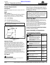
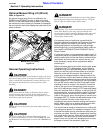
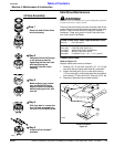
Refer to Figure 1-8:
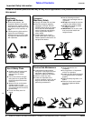
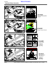
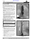
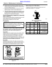
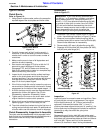
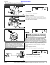
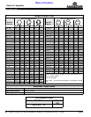
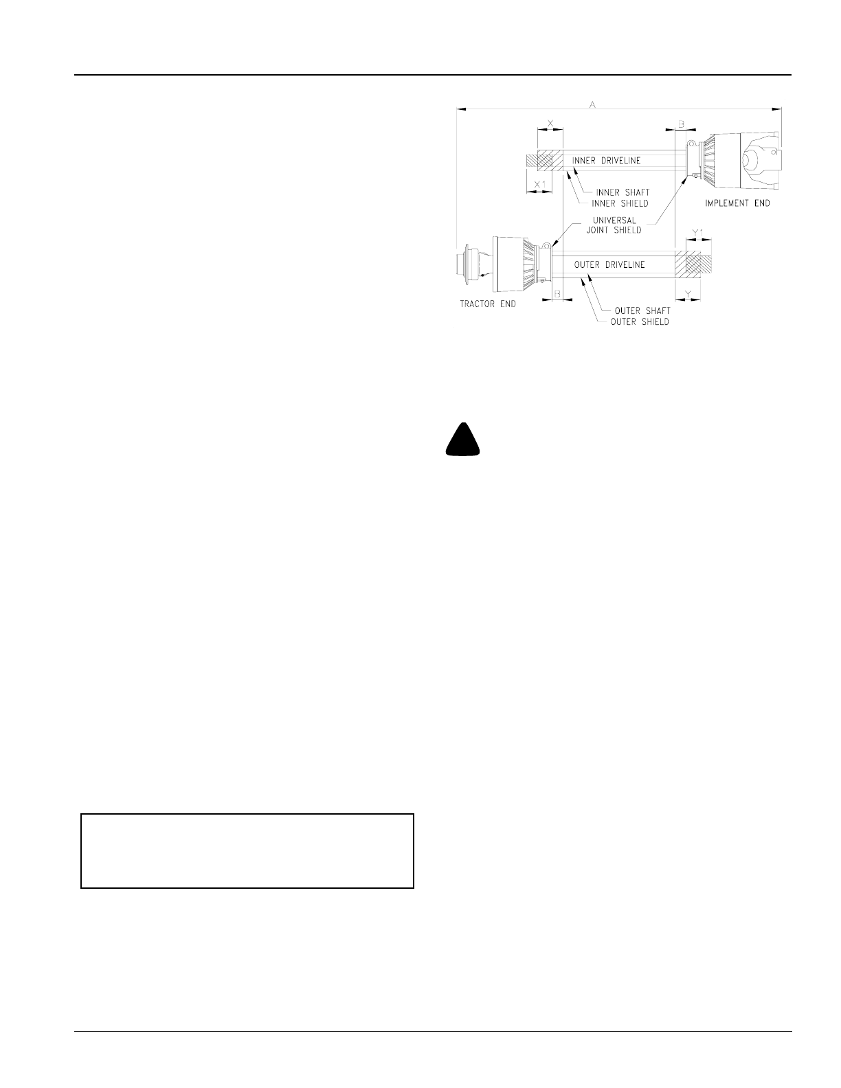
2. The PTO driveline will require shortening if it is too
long to fit between the tractor and cutter gearbox.
Shorten driveline as follows:
a. Place tractor gear selector in park, shut tractor
engine off, set park brake and remove switch key.
b. Pull driveline apart as shown in Figure 1-8 on page
15. Attach the outer yoke section to the tractor
shaft and inner yoke section to the cutter gearbox
shaft. Pull on each driveline section to be sure the
universal joints are secured to the shafts.
c. Hold the driveline sections parallel to each other to
determine if they are too long. The inner and outer
shields on each section should end approximately
1" short of reaching the universal joint shield on the
adjacent section (see “B” dimension). If they are
too long, measure 1"(“B” dimension) back fromthe
universal joint shield and make a mark at this
location on the inner and outer driveline shields.
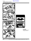
d. Cut off the shield at the mark (“X” dimension). Cut
the same amount off the shaft (“X1” dimension).
Repeat cut off procedure (“Y”&“Y1” dimensions)
to the other driveline half.
e. Remove all burrs and cuttings.
f. Apply multi-purpose grease to the inside of the
outer shaft and reassemble the driveline.
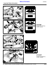
g. Attach inner driveline yoke end to the cutter divider
gearbox input shaft.
h. Attach outer driveline yoke end to the tractor's
shaft.
3. The driveline should now be moved back and forth to
insure both ends are secured to the tractor and cutter
shafts. Reattach any end that is loose.
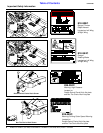
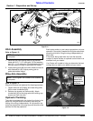
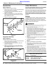
4. Refer to Figure 1-7 on page 14. Secure chain (#6) on
driveline (#5) around the hitch clevis rod to restrict
the driveline outer shield from rotating. Re-latch
safety chain to driveline guard.
5. Attach the safety chain located on the other end of
the driveline (#5) to the cutter’s main frame to restrict
the driveline inner shield from rotating. Re-latch
safety chain to driveline guard.
IMPORTANT: Two small chains are supplied with
each driveline. These chains must be attached to
the outer and inner driveline shields and to the cutter
deck or hitch to restrict the shields from rotating.
PTO Driveline Shortening
Figure 1-8
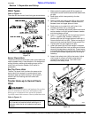
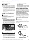
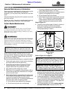
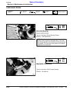
Hydraulic Hook-up
Refer to Figure 1-7 on page 14:
!
DANGER!
Hydraulic fluid under pressure can penetrate skin. Wear
protective gloves and safety glasses or goggles when working
with hydraulic systems. Use a piece of cardboard or wood
rather than hands when searching for hydraulic leaks. If
hydraulic fluid is injected into the skin, it must be treated by a
doctor within a few hours or gangrene may result.
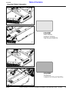
1. Route cylinder hoses (#7) through hose support loop
and connect to tractor remote outlets.
2. Cycle the hydraulic system by raising and lowering
the center deck cylinder and the wing fold cylinders.
It may be necessary to purge the system of trapped
air if operation is sluggish. The system may be
purged as follows:
a. With the wings lowered to the ground, loosen the
hydraulic hose fitting at each wing cylinder slightly
to allow fluid to escape.
b. Slowly activate the tractor control valve to purge
any trapped air from the system.
c. Tighten each fitting.
3. The center deck lift cylinder is purged in the same
manner as the wing cylinders. The lift cylinder must
be fully retracted and the cutter resting on the ground
before loosening the hose fitting as described in
paragraph 2a above.
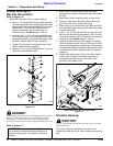
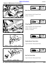
4. Check the driveline for adequate clearance under all
ranges of cutter height. With the driveline shaft
attached to the tractor, slowly raise and lower the
cutter to its upper and lower limits while observing
clearance between hitch and driveline outer shield.
Modify the tractor drawbar height and/or length if the
driveline interferes with the tractor drawbar.
22165