


23
Section 4: Maintenance & Lubrication
9/04/08
RCB6010 & RCB6015 (540 RPM) and RCMB6010 & RCMB6015 (1000 RPM) Rotary Cutters 318-263M
Land Pride
Table of Contents
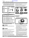
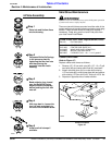
10. If replacing dishpan (#4), nut on gearbox output shaft
should be torqued to 550 ft-lbs. minimum and secured
with a cotter pin installed through the nut and bolt and
both legs bent opposite directions around the nut.
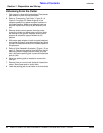
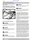
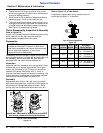
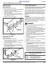
Cutter Blade Assembly
Figure 4-2
Drivelines With Slip Clutches
!
CAUTION!
Engage parking brake, disengage PTO, shut off tractor, and
remove key before working on or around the driveline and/or
slip clutch.
!
CAUTION!
Slip clutches that have been in use or have been slipped for only
two or three seconds during run-in may be too hot to touch.
Allow a hot clutch to cool before working on it.
Cutter drive components are protected from shock loads
by a friction slip clutch. The clutch must be capable of
slippage during operation to protect the gearbox,
driveline and other drive train parts.
Friction clutches should be “run-in” prior to initial
operation and after long periods of inactivity to remove
any oxidation that may have accumulated on the friction
surfaces. Repeat “run-in” instructions at the beginning of
3/4" maximum
blade deflection
when blade
bolts are tight
Land Pride Cutter Blade Parts
Item Part No. Part Description
318-586A BLADE BOLT KIT (Item No’s 1, 2, 5 & 6)
)
1 802-277C BLADE BOLT 1 1/8-12 x 3 7/16 WITH KEY
2 312-075D BLADE SPACER 16 GA. (.06")
2 312-082D BLADE SPACER 18 GA. (.062")
2 312-089D BLADE SPACER 20 GA. (.036")
2 312-808D BLADE SPACER 24 GA. (.024")
3 820-168C CUTTER BLADE 1/2 x 4 x 29 CCW (CTR)
3 820-169C CUTTER BLADE 1/2 x 4 x 23 CCW (RH)
3 820-170C CUTTER BLADE 1/2 x 4 x 23 CW (LH)
4 318-190D WELDMENT DISHPAN
5 804-147C WASHER FLAT 1 HARD ASTMF436
6 803-170C NUT HEX TOP LOCK 1 1/8-12 PLATE
each season and when moisture and/or condensation
seizes the inner friction plates.
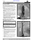
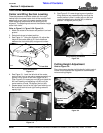
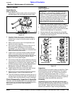
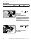
Refer to Figure 5-2 to determine which friction clutch
your cutter has. Follow “run-in” instructions on the
following pages for your specific clutch type.
Clutch Types
Figure 5-2
Type A Clutches
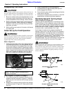
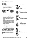
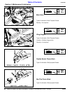
Clutch Run-In
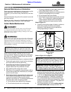
Refer to Figure 5-3:
1. Using a pencil or other marker, scribe a line across the
exposed edges of the clutch plates and friction disks.
Type A Clutch Run-In
Figure 5-3
2. Carefully loosen each of the 8 spring retainer nuts by
exactly 2 revolutions. It will be necessary to hold hex
end of retainer bolt in order to count the exact
number of revolutions.
3. Make sure the area is clear of all bystanders and
machine is safe to operate.
4. Start tractor and engage PTO drive for 2-3 seconds
to permit slippage of the clutch surfaces. Disengage
PTO, then re-engage a second time for 2-3 seconds.
Disengage PTO, shut off tractor and remove key.
Wait for all components to stop before dismounting
from tractor.
5. Inspect clutch and ensure that the scribed markings
made on the clutch plates have changed position.
Slippage has not occurred if any two marks on the
friction disk and plate are still aligned. A clutch that
has not slipped must be disassembled to separate
the friction disk plates. See “Clutch Disassembly,
Inspection & Assembly” below.
Type A Clutch Type B Clutch
23560
Type C Clutch
13693