


14
Section 3: Adjustments
PR1660, PR1672 & PR1690 Powered Rakes 314-216M
10/20/06
Land Pride
Table of Contents
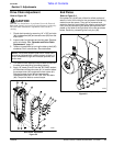
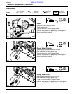
Gauge Wheels
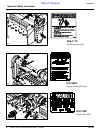
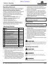
Refer to Figure 3-1
Caster type gauge wheels are mounted on the rake to
control roller height during field operation. Do not use
tractor to control roller height.
Set working depth of the Powered Rake by moving the
gauge wheels up for greater depth and down for less
depth. Move wheels up by repositioning the desired
number of C-spacers located on the gauge wheel
spindles from below the support arms to above the
support arms or from above the support arms to below the
support arms to move the wheels down. For best results,
set the gauge wheel on the chain case side approximately
one inch lower than the non-drive side to allow for
additional weight on the chain case side.
.
Depth Adjustment
Figure 3-1
24527
Rake Angle
The roller framecan be angled a maximum of 15degrees
in either direction for windrowing material to the side.
Angling is accomplished with either a hydraulic cylinder
or a ratchet jack.
Adjust rake angle with a ratchet jack by setting the
ratchet mechanism on the jack andthen pumping the jack
handle.
!
DANGER
Do not operate the hydraulic cylinder controls while someone
is directly behind the tractor or near the Powered Rake.
Adjust rake angle with the hydraulic cylinder by operating
the control lever at the tractor. The hydraulic cylinder
option is very useful when changing rake angle often.
You may order a hydraulic cylinder from your nearest
Land Pride dealer or visit our dealer locator at
landpride.com.
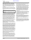
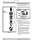
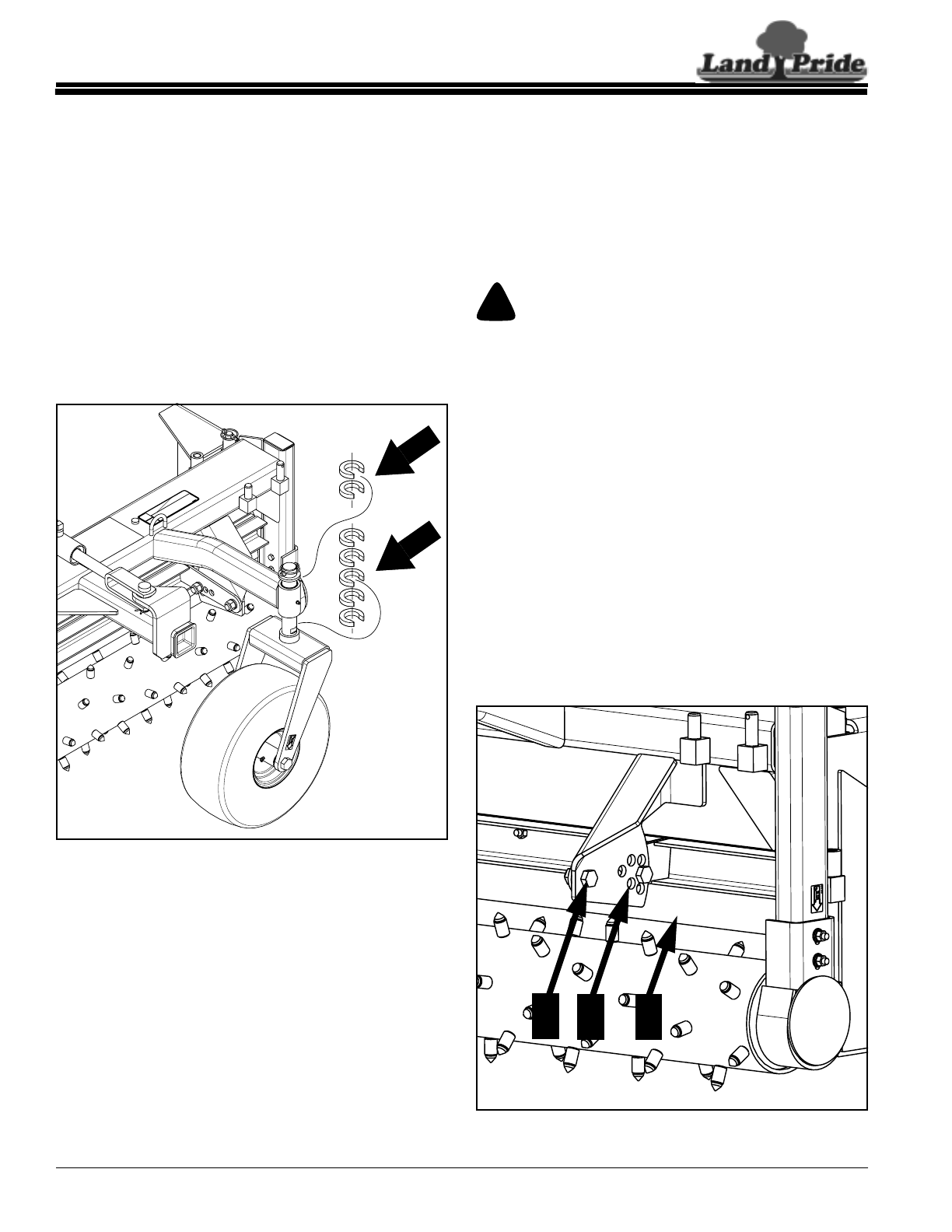
Material Control Deflector
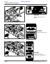
Refer to Figure 3-2
A material control deflector mounted above the rake
roller controls both size and shape of material being
raked by adjusting the height of the deflector above the
roller. The highest position or widest gap allows most dirt
and rock to pass over theroller and lowering the deflector
height or narrowing the gap produces a finer raking job.
Reposition the height of the material control deflector (C)
by loosening at both ends bolts (A) and repositioning
bolts (B) to a different deflector height location.
.
Material Control Deflector Adjustment
Figure 3-2
24509
B
C
A
Section 3: Adjustments