


10
Section 1: Assembly and Set-Up
PR1660, PR1672 & PR1690 Powered Rakes 314-216M
10/20/06
Land Pride
Table of Contents
PTO Hook-Up
If the Powered Rake is to be used on more than one
tractor, an additional PTO shaft may be required -
especially if a quick hitch is used.
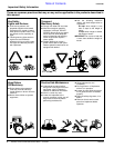
!
CAUTION
Do not use a PTO adaptor with a quick hitch. A PTO adapter
will increase the strain on the tractor’s PTO shaft and can
damage the PTO shaft and driveline.
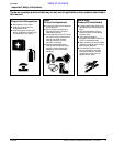
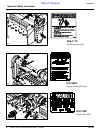
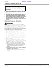
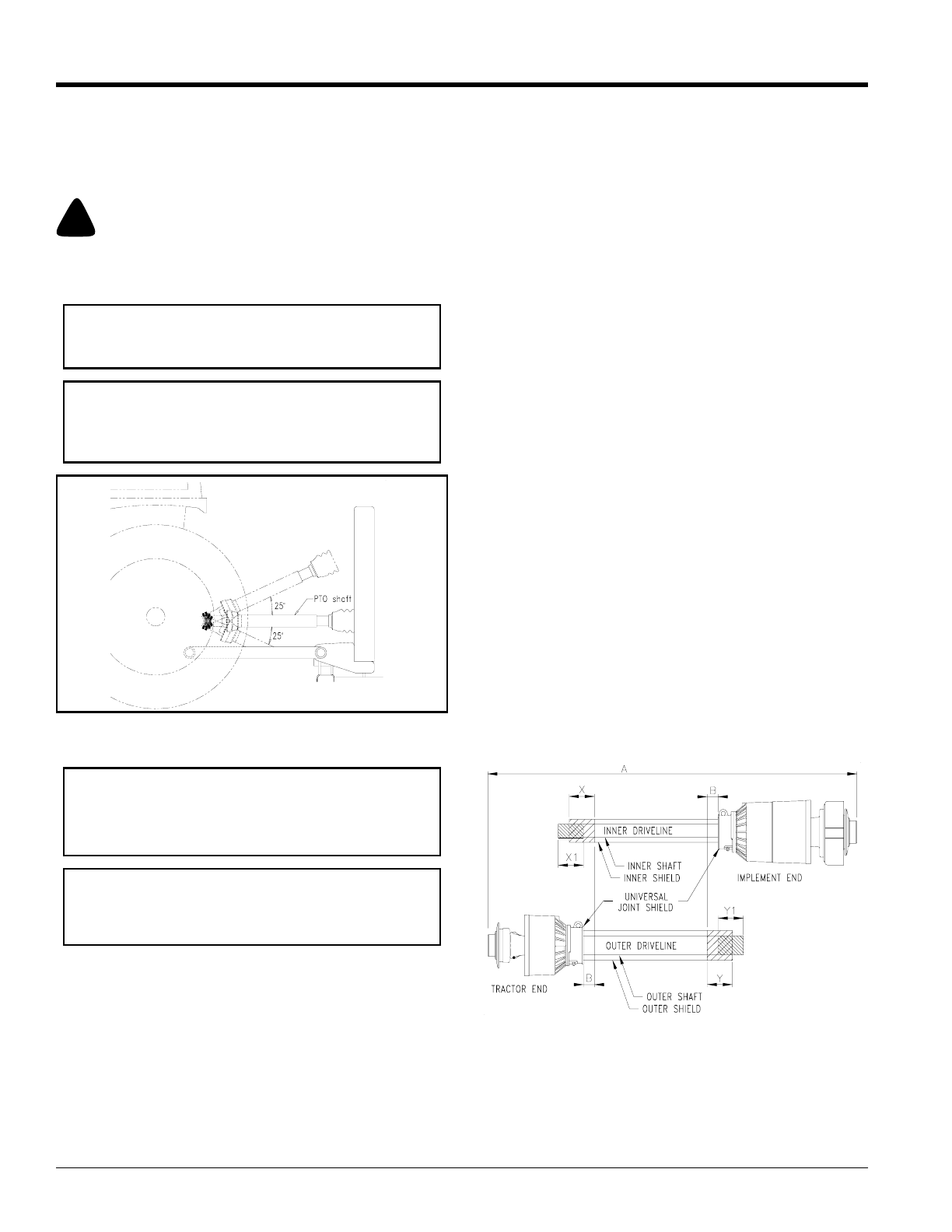
Maximum PTO driveline Movement During Operation
Figure 1-2
Refer to Figure 1-3:
1. Start tractor and slowly engage tractor’s hydraulic
3-point to lift lower arms until the Powered Rake’s
driveline shaft is approximately level with tractor's
PTO shaft.
2. Slide outer yoke end of driveline over the tractor's
PTO shaft and secure with the locking collar. Skip to
step 4 if driveline fits between tractor and Powered
Rake.
IMPORTANT: Some tractors are equipped with
multi-speed PTO ranges. Be certain your tractor ‘s
PTO is set for 540 rpm.
IMPORTANT: Avoid premature driveline
breakdown. A driveline that is operating must not
exceed an angle of 25 degrees up or down while
operating the 3-point lift. See Figure 1-2 below.
13800
IMPORTANT: The PTO driveline may be too long for
some tractors. If the Powered Rake is used on more
than one tractor, an additional PTO driveline may be
required.
IMPORTANT: Aligning the tractor’s PTO shaft level
with the Powered Rake’s PTO shaft is necessary
when checking to see if the driveline will fit correctly
between tractor and Powered Rake.
3. The driveline will require shortening if it is too long to
fit between tractor and Powered Rake. Shorten
driveline as follows:
a. Raise 3-point lower arms until Powered Rake and
tractor PTO shafts are approximately level with
each other. Securelyblock Powered Rake framein
this position. Set tractorin park, shut tractor engine
off, set park brake and remove switch key.
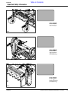
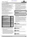
b. Pull driveline apart into two sections as shown in
Figure 1-3. Attach outer driveline universal joint to
the tractor PTO shaft and inner driveline universal
joint to the Powered Rake gearbox shaft. Pull on
each driveline section to be sure the universal
joints are secured to the shafts.
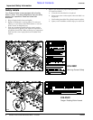
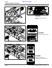
c. Hold driveline sections parallel to each other to
determineif they aretoo long. The inner and outer
shields oneach section shouldend approximately
1" short of reaching the universal joint shield on
the adjacent section (see “B” dimension). If they
are too long, measure 1" (“B” dimension) back
from the universal joint shield and make a mark at
this location on the inner and outer driveline
shields.
d. Cut off the inner shield at the mark (“X”
dimension). Cut the same amount off the inner
shaft (“X1” dimension). Repeat cut off procedure
(“Y”&“Y1” dimensions) to the outer driveline half.
e. Remove all burrs and cuttings.
f. Apply multi-purpose grease to the inside of the
outer shaft and reassemble the driveline.
g. Attach inner driveline yoke end to the Powered
Rake gearbox input shaft.
h. Attach outer driveline yoke end to the tractor's
PTO shaft.
Driveline Shortening
Figure 1-3
4. The driveline should now be moved back and forth to
insure that both ends are secured to the tractor and
Powered Rake PTO shafts. Reattach any end that is
loose.
22227