


24 Section 3 VSC Controller Operation TP-6843 1/13
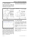
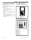
3.2.1 Controller Keypad
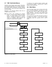
The RUN, OFF, and AUTO buttons control the
generator set as described in Figure 3-3.
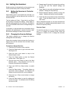
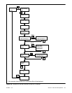
Use the Select, Up arrow, and Down arrow buttons to
navigate through the menus and change settings, if
necessary. See Section 2.4 for operation instructions.
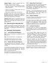
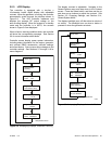
3.2.2 LED Indicators
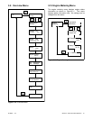
LEDs above the RUN, OFF, and AUTO buttons
indicate the mode of operation as shown in Figure 3-4.
Load indication LEDs indicate the load on the
generator set. A steadily lighted LED indicates that
the load on the generator set is greater than or equal
to the level label for that LED. The next LED flashes
and stays on for a longer time as the load increases.
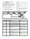
Figure 3-3
Figure 3-3 VSC Controller Pushbutton Operation
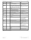
Figure 3-4
Figure 3-4 VSC Controller LED Operation
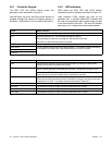
Button Button Function
RUN Starts the generator set. The engine start time delay is ignored.
OFF Stops the generator set. The cooldown time delay is ignored.
During the engine crank cycle, pressing OFF will stop the crank cycle.
Press OFF to clear faults and reset the controller.
AUTO Places the generator set in Automatic (standby) mode.
Down arrow Use to navigate through menus and change settings. This manual contains instructions
to navigate the controller menus and adjust settings on the VSC controller.
Select
Up arrow
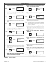
LED LED Operation
RUN Lights when the generator set has been started locally by pressing the RUN button.
Remote start and stop commands are ignored.
OFF Lights for 2 seconds, then flashes every 2 seconds when the generator set and controller
are off. Remote start/stop commands have no effect. The exercise cycle will not run.
In Auto mode, OFF LED flashes quickly to indicate a fault shutdown. Attention required.
Identify and correct the fault condition before resetting the controller.
AUTO Lights when the generator is in automatic (standby) mode. Generator set will respond to
engine start and stop commands from the controller (for example, exercise start and stop
commands) or an ATS. Time delays operate as described in Section 2.4.
25% load LED flashes and stays on longer as load increases from 1% to 25%.
50% load LED flashes and stays on longer as load increases from 26% to 50%.
75% load LED flashes and stays on longer as load increases from 51% to 75%.
100% load LED flashes and stays on longer as load increases from 76% to 100%.