


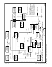

TP-5700 7/9336 Section 7 Electrical Requirements
7.2 Electrical Connections
Several electrical connections must be made between
the generator set and other components of the system
for proper operation. Because of the large number of
accessories and possible combinations, this manual
does not address specific applications. Refer to the
submittal catalog accessory drawings and wiring
diagrams for connection and location. Most
field-installed accessory kits include installation
instructions.
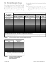
For customer-supplied wiring, select the wire
temperature rating in Figure 7-2 based upon the
following criteria:
D Selectrow1,2,3,or4ifthecircuitratingis
110 amperes or less or requires #1 AWG (42.4 mm
2
)
or smaller conductors.
D Select row 3 or 4 if the circuit rating is greater than
110 amperes or requires #1 AWG (42.4 mm
2
)or
larger conductors.
Comply with applicable national and local codes when
installing a wiring system.
Row Temp. Rating Copper (Cu) Only Cu/Aluminum (Al) Combinations Al Only
1
60_C (140_F)
or
75_C (167_F)
Use No. * AWG, 60_C
wire or use No. * AWG,
75_Cwire
Use 60_C wire, either No. * AWG Cu, or
No. * AWG Al or use 75_C wire, either
No.*AWGCuorNo.*AWGAl
Use 60_Cwire,No.*
AWG or use 75_Cwire,
No. * AWG
2
60_C (140_F) Use No. * AWG, 60_C
wire
Use 60_C wire, either No. * AWG Cu or
No. * AWG Al
Use 60_Cwire,No.*
AWG
3
75_C (167_F) Use No. *[ AWG, 75_C
wire
Use 75_C wire, either No. * [ AWG Cu or
No. *[ AWG Al
Use 75_Cwire,No.*[
AWG
4
90_C (194_F) Use No. *[ AWG, 90_C
wire
Use 90_C wire, either No. * [ AWG Cu or
No. *[ AWG Al
Use 90_Cwire,No.*[
AWG
* Thewire sizefor 60_C (140_F)wire isnot requiredto beincluded inthemarking. If included,thewire sizeis basedonampacities for thewire
given in Table 310-16 ofthe National Electrical Coder, in ANSI/NFPA70, and on 115% of themaximum current that thecircuit carries under
rated conditions. The National Electrical Coder is a registered trademark of the National Fire Protection Association, Inc.
[ Usethelargerofthefollowingconductors: thesamesizeconductorasthatusedforthetemperaturetestoroneselectedusingtheguidelinesin
the preceding footnote.
Figure 7-2 Terminal Markings for Various Temperature Ratings and Conductors
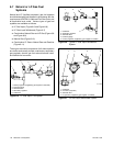
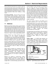
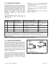
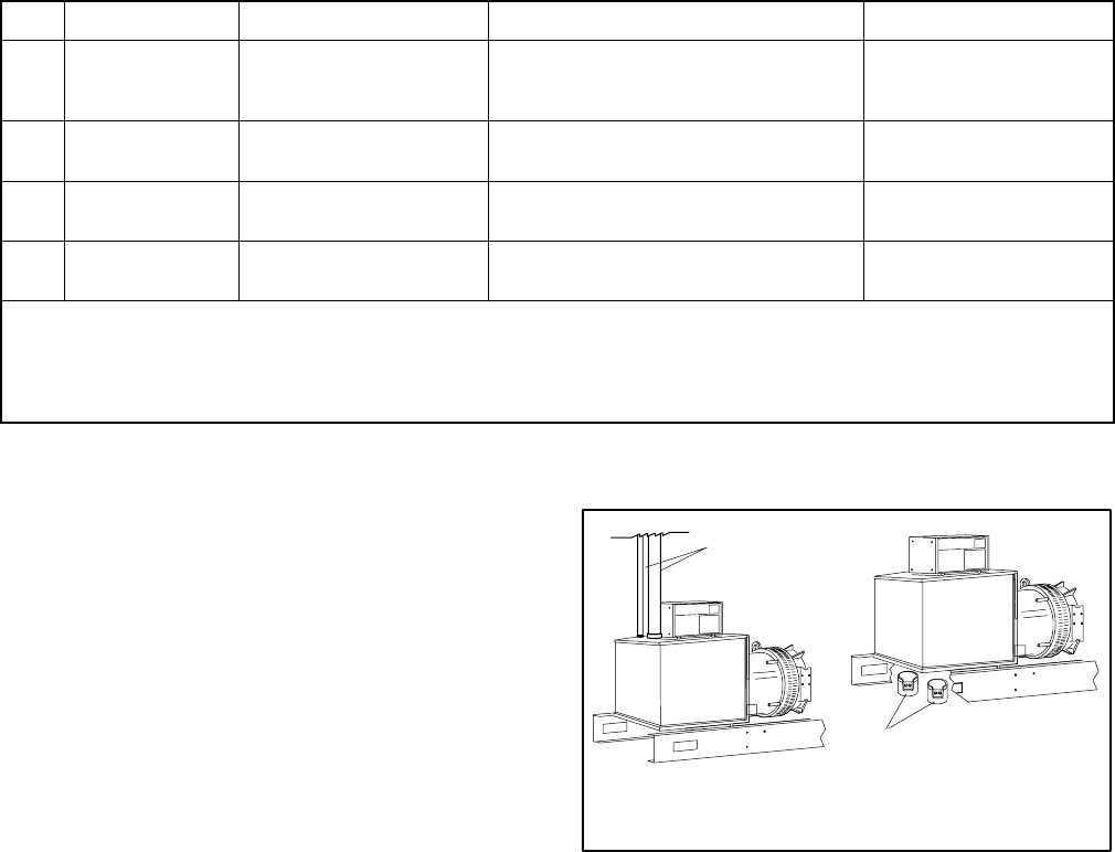
7.3 Load Lead Connections
Load leads being broughtinto the generator can enter in
a number of different areas. On generators 300 kW and
below the most commonly used is the bottom entry,
where conduit is “stubbed up” into the junction box from
below. Other methods include flexible conduit roughed
into the sides or top of the junction box. When using this
method, be sure not to block the front or rear of the
controller,as doingso willprevent accessto itfor service
purposes. See Figure 7-3.
On generators larger than 300 kW, a junction box is
mounted on the rear of the generator. Larger sets may
have oversize junction boxes suppliedas an option or to
accommodate buss bar connections. Consult the
dimensional drawing on your unit for detailed
information.
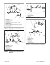
TP-5700-7
1
2
1. Conduit from ceiling
2. Conduit stubbed up from below
Figure 7-3 Typical Load Lead Connection