TP-5700 7/9318 Section 4 Air Requirements
The engine water pump can be used to circulate water
through the r emote radiator providing that the vertical
distance f rom t he engine water pump does not exceed the
engine manufacturer’s recommendations. The allowable
static head may range from 17-50 feet (5.2-15.2 m).
Consult the Specification Sheet for the unit. T his is
important because greater height will result in excessive
head pressure on engine components, causing problems
such as leaking water pump seals. T he piping between the
engine and remote radiator must be sized for a maximum of
2 psi (0.141 kg/cm
2
) pressure drop at the rated flow of the
engine water pump. A vent line from the engine to the
radiator may be necessary to purge air from the cooling
system.
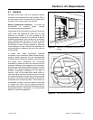
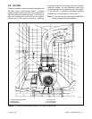
When either horizontal or vertical distances exceed the
above limitations, a hot well tank or heat exchanger and
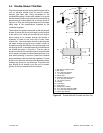
auxiliary circulating pump as shown in Figure 4-10
should be used. The circulating pump should always be
wired in parallel with the remote radiator fan so that both
will operate whenever the generator set operates.
Heated water is forced by the engine pump into the “hot”
side and then is drawn off by the auxiliary pump and
forced into the radiator. After circulating through the
radiator, coolant flows back to the cold side of the well
where it is removed by the engine water pump. Head
pressures are thus isolated from the engine. Pressure
can also be isolated by installing a heat exchanger
between the engine and remote radiator.
With the radiator at a remote location, it is easily
overlooked each time the generator is serviced. For this
reason, low water alarms, or automatic “make-up”
controls are often included in these systems. Antifreeze
is required if the radiator is subject to freezing
temperatures.
Shutoff valves should be located between the engine
and cooling system to allow for isolation of both
systems. This will eliminate the need to drain the entire
system during service.
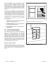
To determine radiator size and air requirements check
the Specification Sheet for your model. The amount of
air required to ventilate the generator set room or
enclosure determines the size of the air inlet and
outlet—a ventilating fan is usually necessary as
generator heat loss as well as engine heat loss must be
dissipated.
4.9 City Water Cooling
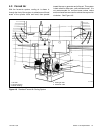
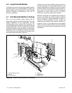
These systems utilizes city water and heat exchangers
for cooling and are similar to remote radiator systems in
that they require less cooling air than unit-mounted
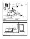
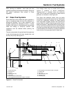
radiator systems. Refer to Figure 4-11 for a view of
some of the elements of a typical installation.
The heat exchanger the effects of city water (lime
deposits, corrosion) to one side of a heat exchanger
which is relatively easy to clean or replace, while engine
coolant circulatesin a closedsystem similar to aradiator
system.
It allows better control of engine temperature, permits
the use of antifreeze and coolant conditioners, and is
suited to the use of an engine block heater as a starting
aid.
Water inlet and outlet connections are mounted on the
generator set skid and isolated from engine vibration by
flexible sections. If the generator set is vibration-
mounted to the skid and the skid is bolted directly to the
mounting base, no additional flexible sections are
needed between connection points on the skid and city
water lines. If the generator set skid is mounted to the
base with vibration isolators, flexible sections must be
used between connection points on the skid and city
water lines.
A solenoid valve mounted at the inlet connection point
automatically opens upon start-up of the generator set,
providing water under pressure from city mains for
engine cooling. This valve automatically closes when
the unit shuts down. Be sure that the solenoid valve is
located upstream of the supply flexible connection. An
additional customer-supplied valve may be used ahead
of the entire system to manually shut off city water when
servicing the generator.
4.10 Cooling Tower
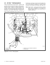
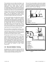
In warm, dry climates, a cooling tower may be a suitable
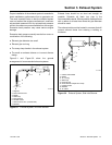
source of generator set cooling water. A typical system
is shown in Figure 4-12. This is a variation of the city
water cooling with heat exchanger. The engine system
usually includes the engine water pump, a heat
exchanger, a surge tank, and the water jacket of the
engine. The raw water system consists of the cooling
tower,a raw waterpump, andthe tubeportion ofthe heat
exchanger. Raw water is circulated through the heat
exchanger tubes to absorb heat from the enginesystem
which is circulated around the surrounding shell of the
heat exchanger. The heated raw water is directed into a
pipe at the top of the cooling tower and sprayed down
into the tower to cool by evaporation. Since some water
is constantly being lost by evaporation, the systemmust
include provision for “make up” water.


