TP-5700 7/93 21Section 5 Exhaust System
Section 5 Exhaust System
Proper installation of the exhaust system is essential to
obtain satisfactory performance from a generator set.
The most important factor is that the installed system
must not exceed the engine manufacturer’s maximum
exhaust backpressure limit. Anyexhaust back pressure
will limit the maximum power available from the engine.
Excessive back pressure may cause serious engine
damage.
Excessive back pressure usually results from one or a
combination of the following:
D Exhaust pipe diameter too small
D Exhaust pipe too long
D Too many sharp bends in the exhaust system
D Too small an exhaust silencer or incorrect silencer
design
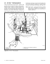
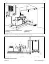
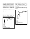
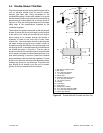
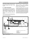
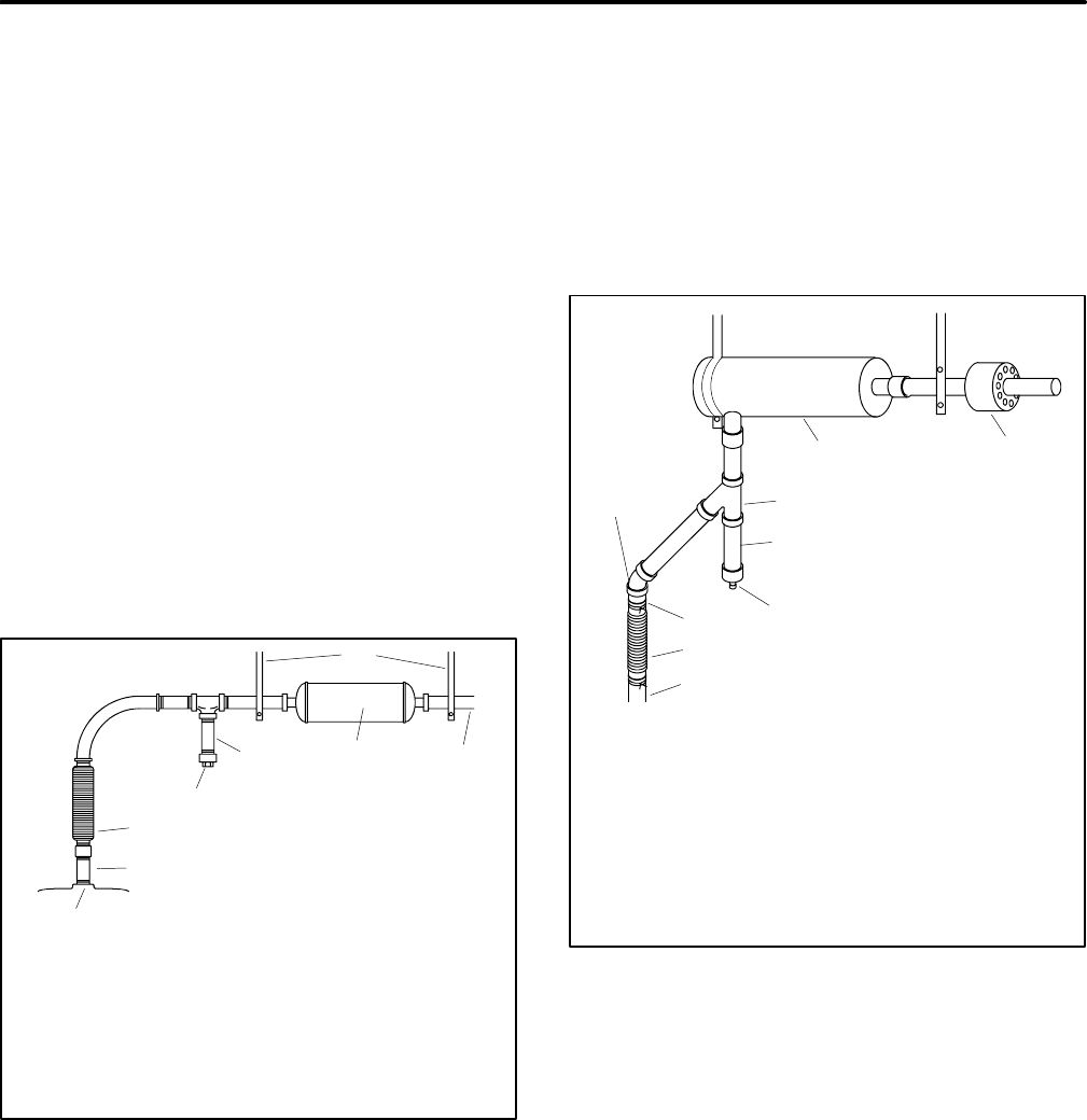
Figure 5-1 and Figure 5-2 show the general
arrangement of recommended exhaust systems.
1
3
2
4
5
6
7
8
TP-5700-5
1. Supports
2. Pitch line downward
3. Muffler
4. Water trap
5. Drain petcock
6. Flexible section
7. Solid section 6--8 in. (152--203 mm)
8. Manifold
Figure 5-1 Exhaust System, End Inlet Silencer
Exhaust lines should be as short and straight as
possible. Schedule 40 black iron pipe is the
recommended material. Where possible, sweep elbows
with a radius of at least three times the pipe diameter
should be used.
The exhaust outlet must be located in a manner that will
prevent exhaust fumes from entering a building or
enclosure.
3
7
6
1
2
9
8
TP-5700-5
1. Exhaust wall thimble
2. Muffler
3. 45° Y fitting
4. Water trap
5. Drain petcock
6. Outer diameter adapter and clamp
7. Flexible section
8. Manifold
9. 45° elbow
4
5
Figure 5-2 Exhaust System, Side Inlet Silencer


