TP-5700 7/9332 Section 6 Fuel Systems
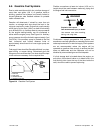
6.8 Flexible Connector
An approved flexible connector should always be used
between stationary gas piping and the engine-mounted
fuel system components. It should be at least six inches
(15.3 cm) long or as recommended by the generator
supplier based upon engine specifications.
6.9 Gas Piping
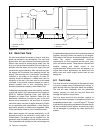
Gas piping should be Schedule 40 black iron pipe.
Copper tubing may be used if the fuel does not contain
hydrogen sulfide or other ingredients which will react
chemically with copper. Fuel piping should never be
used to ground electrical equipment. Piping should be
sized according to the requirements of the equipment to
be operated. Refer to the dimensional drawing for
detailed information on your unit. In addition to the
actual fuel consumption, the following factors must be
considered:
D Pressure loss due to length of pipe
D Pressure loss due to other appliances on thes ame
fuel supply
D Pressure loss due to number of fittings
6.10 Fuel Regulators
Fuel regulatorsare compatible withboth naturalgas and
LP gas. When used with natural gas the spring and
retainer are installed. The spring and retainer are
usually removed from the fuel regulator when used with
LP gas. Refer to the appropriate generator set
operation manual and/or decal on the unit for specific
information regarding spring/retainer usage.
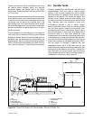
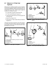
Gas fuels may require the fuel regulator to be mounted
in a given position. The fuel regulator will function
properly with the fuel regulator pointing downward for
both natural gas and LP gas. The fuel regulator may be
positioned so that it is pointing upward for use with
natural gas only.
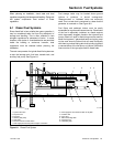
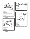
Two regulators are used in the typical gaseous fuel
system:
D Primary Regulator—This regulator provides initial
control of the gas from the fuel supply. The primary
regulator reduces line pressures to allowable inlet
pressures for the secondary regulators on the
system. This regulator would drop high pressure
from a tank or transmission line to a low pressure,
typically 4-6 ounces per square inch (1.7-2.6 kPa)
or 7-11 inches (178-279 mm) ofwater column. This
regulator is not usually supplied with the generator
set, as conditions that dictate the type used vary
depending on the method in which the fuel is
supplied.
D Secondary Regulator—This low-pressure type
regulator ismounted on the engineand is designed
for a maximum inlet pressure of six ounces per
square inch (2.6 kPa) or 11 inches (279 mm) of
water column. The engine will operate
satisfactorily at four ounces per square inch
(1.7 kPa) or 7 inches (179 mm) of water column or
less, but lower pressures may result in poor
response to load changes or lack of power where
the primary regulator is not near the engine.
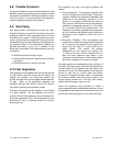
Although regulators are designed to close and shut off
fuel when the engine stops, a solenoid valve should be
located ahead of the regulator and the flexible fuel
connector to prevent the accumulation of an explosive
mixture of gas and air, should either the flexible
connection or regulator develop a leak. The generator
set installer normally wires the solenoid valve to the
engine starting controls so it will open (with battery
power) when the engine cranks or runs.
Some fuel regulators have provisions to install a
pressure gaugeto test inletand outlet pressures.If none
are available,install pipe teesin the fuelline to servethis
purpose and use pipe plugs on any unused openings.


