TP-5700 7/9316 Section 4 Air Requirements
4.6 Liquid-Cooled Models
The three most common liquid cooling systems used for
generator setsare unit-mounted radiator, city water, and
remote radiator cooling. Since each involves somewhat
different installation considerations, they will be
discussed separately.
4.7 Unit-Mounted Radiator Cooling
This is the most c ommon c ooling system used for
engine-driven generator sets 20 kW and larger. T he major
system components are an engine-driven fan and
circulating water pump, a radiator , and a thermostat. The
pump circulates water through the engine until it reaches
operating temperature. Then the engine thermostat opens
and allows circulation through the radiator . It can also close,
restricting the flow as necessary to prevent overcooling.
The fan blows air from the engine side of the radiator across
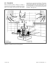
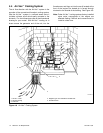
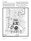
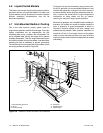
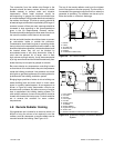
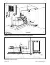
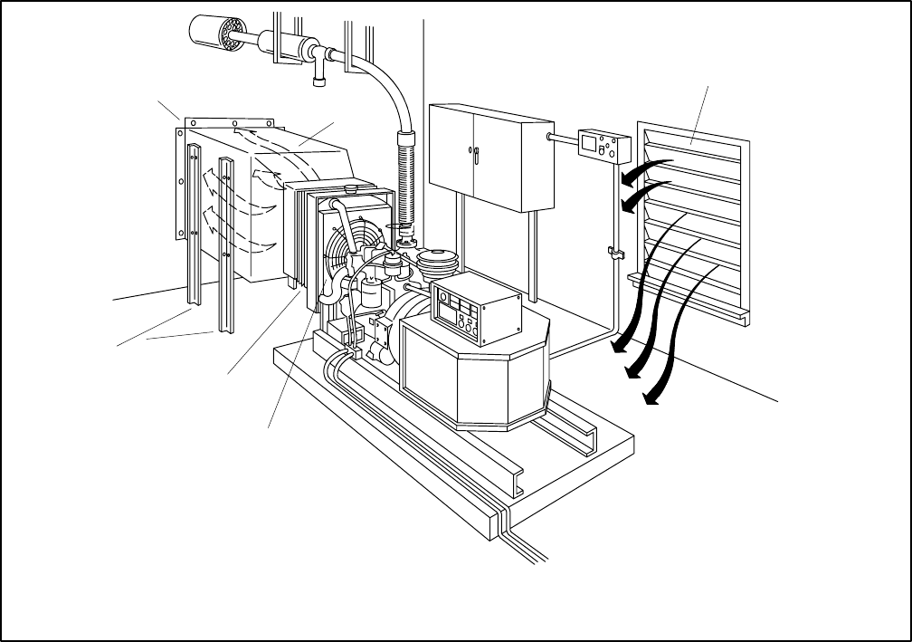
the c ooling surface as s hown i n F igure 4-8.
Cooling air flow can be reversed by using a suction fan,
but this is generally not recommended because it may
interfere with generator cooling air flow, which moves in
the same direction as the engine’s standard pusher fan.
Also, a suction fan would result in higher temperature
combustion air being drawn into the air cleaner,
reducing the maximum engine power available.
Whenever a generator set is installed inside a building or
enclosure, the radiator air should be ducted outside the
room or enclosure. A typical arrangement is shown in
Figure 4-8. Ductwork should be as short, straight, and
unobstructed as possible. Static pressure restrictions of
more than 1/2 i nch (1.3 cm) water column o n t he radiator
outlet o r i nlet air will reduce a ir flow to the point of limiting
maximum power and/or ambient temperature that causes
overheating.
7
8
9
10
11
12
7. Self-supporting duct work
8. Air out
9. Air inlet opening
10. Pusher fan
11. Flexible section
12. Support legs
Figure 4-8 Radiator-Cooled Generator Set Installation


