ASSEMBLY
OM 0369SB1148-A 18
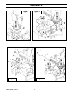
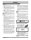
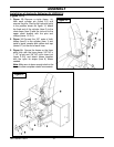
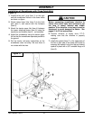
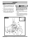
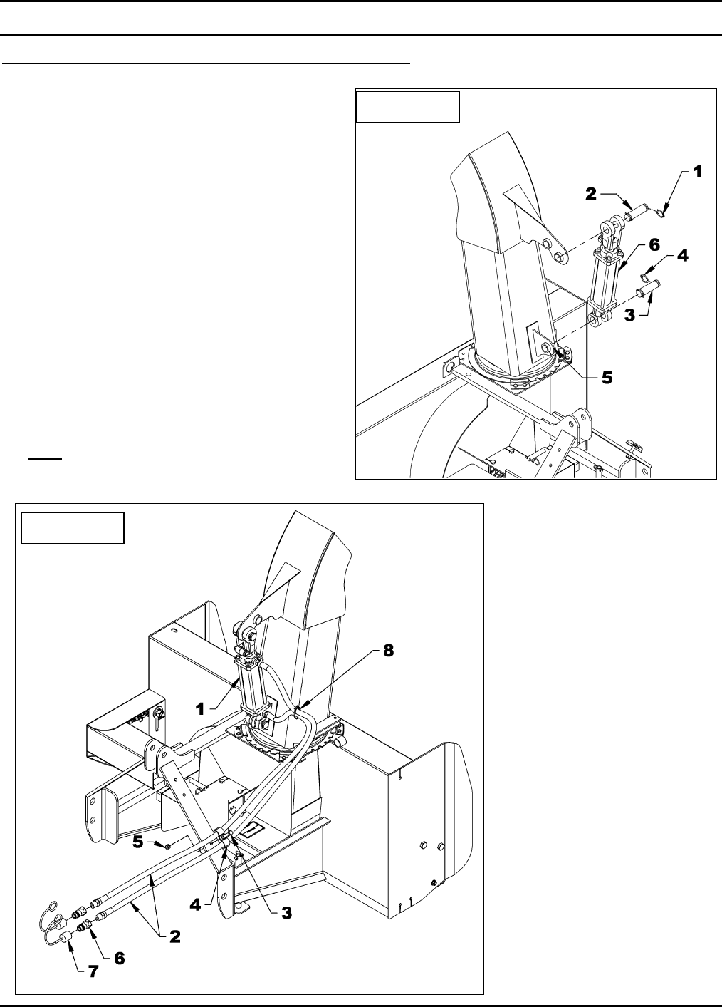
Installation of Hydraulic Deflector Kit 5RDF0019
(Figures 13-14)
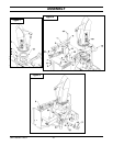
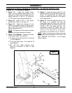
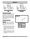
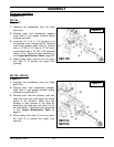
1. Figure 13: Remove a circlip (items 1-4)
from each cylinder pin (items 2-3) and
remove the pins. Placing the hydraulic ports
in the position shown on figure 14, attach
the fixed end of the cylinder (item 6) to the
chute base (item 5) and the rod end to the
upper chute bracket with the pins and
circlips (items 1-2-3-4).
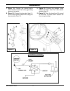
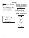
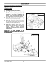
2. Figure 14 Connect the 3/8" ends of both
hoses (item 2) to the cylinder (item 1) and
install a quick coupler with rubber dust cap
(items 6-7) at the end of each hose.
3. Figure 14: Secure the hoses on the three
point hitch with the hose clamp, 3/8" NC x
1 1/2" lg bolt and 3/8" NC nylon insert nut
(items 4-3-5) and attach hoses together
with the nylon tie wraps (item 8) where
needed.
Note: Make sure to leave enough slack to the
hoses to allow complete rotation movements.
Figure 13
Figure 14


