


ASSEMBLY
OM 0369SB1148-A 12
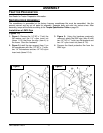
Installation of Chute and Manual Rotation Kit 5RDF0016
(Figures 3-4-5-6)
NOTE: The rotation handle can be installed
on the right or left side of the three point
hitch.
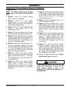
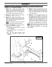
1. Figure 3: Install the rotation bushing
(item 2) over the chute base.
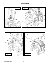
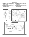
2. Figure 4: Insert the 1 11/16" plastic
bushing (item 1) in the worm support
bracket (item 2) and insert the longest end
of the rotation worm (item 3).
3. Figure 4: Insert the 1 5/16" plastic bushing
(item 4) in the welded tube of the
snowblower (item 5).
4. Figure 4: Place the support (item 2) under
the snowblower's right upper plate (item 6).
5. Figure 3: Place the chute (item 1) over the
rotation bushing (item 2) and install the four
retaining plates (item 3) with eight 1/4" x
3/4" bolts and eight serrated flange nuts
(items 4-5). Tighten securely.
6. Figure 4: Insert the rotation tube (item 7) in
the worm assembly aligning the holes,
insert an Allen socket head capscrew 10-24
x 1" (item 8) making sure the screw head
sinks into the rotation worm and secure
with a nylon insert nut (item 9).
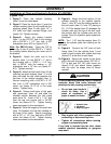
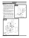
7. Figure 5: Install the rotation bracket
(item 1) on the left or right arm of the three
point hitch with two 3/8" NC x 1 1/4" bolts,
3/8" lockwashers and 3/8" nuts (items 2-3-
4). Tighten firmly.
8. Figure 5: Attach the handle support
bracket (item 5) to the rotation bracket
(item 1) with a 3/4"NC x 1 1/4" bolt,
lockwasher and nut (items 6-7-8) making
sure to attach the brackets in the direction
illustrated.
9. Figure 5: Insert the handle support (item 9)
in the bracket (item 5) adjusting the height
of the support according to your needs and
secure in place with a 3/8" x 1/2" square
head setscrew (item 10).
10. Figure 5: Insert the grommet (item 11) in
the handle support (item 9).
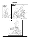
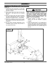
11. Figure 6: Insert the handle (item 1) in the
handle support (item 4) and in the rotation
tube. Select desired length, align nearest
holes and secure with the 4 mm x 80mm
hairpin (item 2). Install the plastic handle
(item 3).
12. Figure 5: Once the snowblower is attached
to the tractor, adjust handle position and
height to ensure comfort and safe
operation. Tighten setscrew (item 10) on
the handle support as well as the 3/4" x
1 1/2" bolt, 3/4" lockwasher and 3/4" nut
(items 6-7-8).
13. Figure 6: To insure the manual rotation
functions properly, position the handle
support (item 4) the closest possible to the
top link mounting point of the three point
hitch while making sure it does not come
into contact with the operator's seat when
the snowblower is fully raised.
14. Tighten all bolts according to the Torque
Specification Table on page 50.
CAUTION
To avoid personal injury, check the full lifting
range of the snowblower, to ensure that the
chute rotation handle is clear of the
operator’s area when the snowblower is in
raised position.