


ASSEMBLY
OM 0369SB1148-A 16
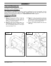
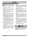
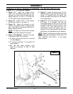
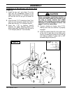
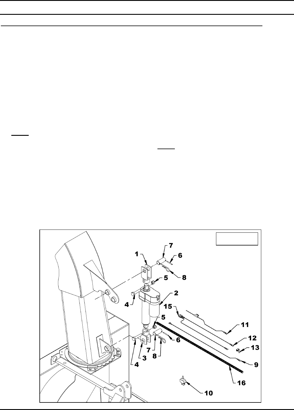
Installation of Electric Deflector Kit 5RDF0020 – For SB1154 & SB1164 Only
(Figures 10-11-12 & Electrical Diagram)
1. Figure 10: Install the longest clevis
(item 1) on the actuator base (item 2), the
shortest one (item 3) on the other end and
attach using two 1/2" NC x 2 1/2" bolts and
1/2" NC nylon insert locknuts (items 4-5).
2. Figure 10: Install a 3/16" x 1 3/4" spring
pin (item 6) on each 1" pin (item 7).
3. Figure 10: Attach the actuator on the
chute in the position shown on figure using
two 1" pins (item 7) and secure with 4mm x
80mm hairpins (item 8).
NOTE: The base end of the electric actuator
attaches in the hole closest to the chute.
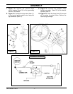
4. Figure 10 & diagram: Connect the wires
to the switch (item 10) as follows:
• 72" black ground wire (item 9) to terminal
"C" (see diagram).
• 72" red fuse wire (item 11) to terminal "B
(see diagram).
• 360" red and black actuator wires
(item 12) to terminal "A" and "D" (see
diagram).
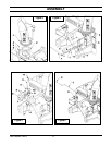
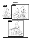
5. Figure 11: Insert the switch (item 4) in the
switchbox (item 2), secure with the two nuts
(items 1-3) supplied with the switch and
screw the rubber cap (item 5) on the switch
in the order shown.
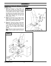
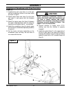
6. Figure 12: Place the switchbox (item 1) on
the lever in a position that will be
comfortable when the hand is on the knob
and attach with the box clamp (item 5), two
1/4"NC x 3/4" hex. bolts and two 1/4"
lockwashers (items 3-4) making sure the
clamp is in the right direction so the lower
openings on the switchbox are not blocked.
NOTE: Tighten the bolts just enough to securely
fix the clamp and the switchbox on the lever. DO
NOT TIGHTEN TOO MUCH so the clamp
doesn't deform.
Figure 10