


5
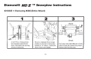
CRANKSTAND STORAGE
To store Crankstand on the Lift Frame slide the tube that is attached
to the side of the Crankstand over the receiver tube on the driver's
side of the Lift Frame. Insert the chain locking pin through the vertical
holes on both the tubes. Note: Crankstand should always be fully
retracted (up) and be pinned in the vertical transport position
when not In use. Receiver Tube Cap may be placed over the driver
side transport tube while the Crankstand is in use on the A-Frame.
The Receiver Tube Cap may also be switched over to the Adjustment
Tube of the A-Frame when the Crankstand is mounted to the Lift
Frame.
Storage of the Crankstand is the responsibility of the operator.
The stand can be stored on the lift frame in the retracted
position to the driver's side transport tube or inside the vehicle
cab.
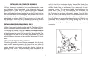
HYDRAULIC COVER
Install Black Hydraulic Cover before installing the Lift Assembly to
the Lift Frame. Begin by sliding the Hydraulic Cover down over the
Lift Ram. Slide the side covering the motor carefully over the motor,
do not force or stretch the Hydraulic Cover; it will fit comfortably over
all parts of the Hydraulic Unit. Feed the three coil wires (red, green
and black) through the hole located on backside of cover. Route
coupler weather plugs through holes in cover where power angling
hoses enter. Snap Cover together. Caution: Care should be taken
with the installation and or removal of the Hydraulic Cover, including
partial removal when repairs are performed on the Hydraulic Lift Unit.
Tearing of the Hydraulic Cover for any reason will not be covered
under the Diamond Warranty.
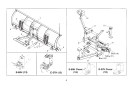
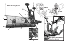
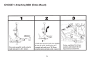
ATTACHING MOLDBOARD ASSEMBLY ONLY
Attach A-Frame to Lift Frame by connecting Crankstand to the
adjustment tube in the center of the A-Frame Frame. Insert the
chained locking pin all the way through the vertical holes on both the
tubes. Crank up A-Frame until the holes on the back ears of the A-
Frame are about 12” off the ground. Pull out the Yellow Handle Pins
on both sides of the Lift Frame. Twist handle slightly to the right or
left disengaging the pin. Pull truck up to the A-Frame / Moldboard
assembly aligning the A-Frame ears between the two lift frame plates
until contact is made with the Clevis Frame. Once you feel contact,
push the moldboard assembly a few inches forward, this insures
proper alignment so that the A-Frame is square to the Clevis Frame.
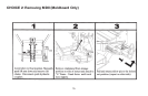
Adjust the Crankstand up until the front of the truck raises slightly.
Rotate the Yellow Handled Pins so that the small leg realigns with the
slot, engaging the pin. The spring loaded pin should snap into place
locking the A-Frame to the lift frame. Note: If pins do not properly
engage move the truck slightly forward a few more inches and/or
adjust (raise or lower) the Crankstand until pins lock into place. If
only one pin should engage, retract the stand to the full upright
position. Remove the Crankstand from the A-frame by removing the
chained locking pin. Reattach the Crankstand to the transport tube
on the driver's side of the Lift Frame in the vertical transport position.
Attach the Lift Chain to the Lift Arm through the two hooks on the lift
arm. Adjust the lift chain at the lift arm so that there are 2-3 links of
slack. This ensures that the plow blade will lift fully and be able to
follow the ground contour while plowing. Raise the plow with the
hydraulics and swing the moldboard slightly left or right until the pin
engages.