


20
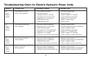
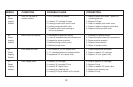
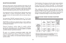
TROUBLESHOOTING CHART FOR ELECTRIC HYDRAULIC POWER UNITS
This chart is intended to be used as an aid in diagnosing problems on Diamond Hydraulic Power Units. It is not a substitute for factory training and
experience. Be certain to read the General Information and Testing Tips sections before attempting any troubleshooting. Additional detailed
information as well as all electrical schematics may be found in Service Manuals 1-667 (E-60, E-60H) and E-57H.
GENERAL INFORMATION
Before any troubleshooting is started, make certain the following conditions are met.
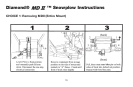
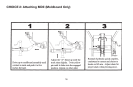
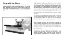
1. The moldboard is pointing straight ahead. This can often be done by coupling the hose from the left cylinder into the right cylinder and pushing
the snowplow by hand.
2. The power angling cylinders must be installed correctly. The left cylinder has a hose with a male half of a coupler attached while the right
cylinder only has the female half of a coupler attached. Reverse them if installed on wrong side.
3. The solenoid coils must be on their proper valve. The "C"- coil (green wire) must be located on the valve closest to the power angling hoses.
The "B"-coil (red wire) is positioned on the valve furthest from the power angling hoses. The “A” coil (black wire) is smaller in diameter and is
easily located on the E-60 power unit. On the E-57 power unit, the "A" coil (black wire) is located on the back side of the unit.
4. The electrical installation must have been made according to instructions supplied by Diamond Equipment.
TESTING TIPS
Many tests do not require removing the Power Unit from the vehicle. However, more thorough testing can be done by using the Meyer Test Stand
which allows direct pressure and Amperage readings.
1. Use a screwdriver or other small tool to check for magnetism of solenoid coils “A”, “B” & "C". Place the tool on the nut securing the coil and
have an assistant operate the switch. You should feel strong magnetic attraction.
2. Use a test light or volt meter to determine whether there is power at harness or switches.
3. When determining Ampere draw of motor, always obtain the highest value possible, i.e., at maximum raise or angle with motor running.
4. Proper rotation for motor is indicated by an arrow on the top of the E-57 pump.
5. The pump shaft (all models) of a good pump can be turned smoothly using two fingers. If it can't be turned easily, the pump is too tight and
must be replaced.
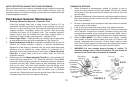
6. Pump pressure can be measured at an angle hose (note pressure at full angle) or in the pressure filter port (an adapter is necessary for the filter
port). (See Figure 0-3.)
7. If hydraulic system is contaminated it is recommended that the hydraulic unit, power angling rams and hoses be drained and flushed clean.
The system should then be refilled with Meyer M-1 oil. See pages 18-19.