


54
J-300
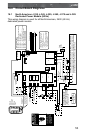
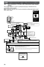
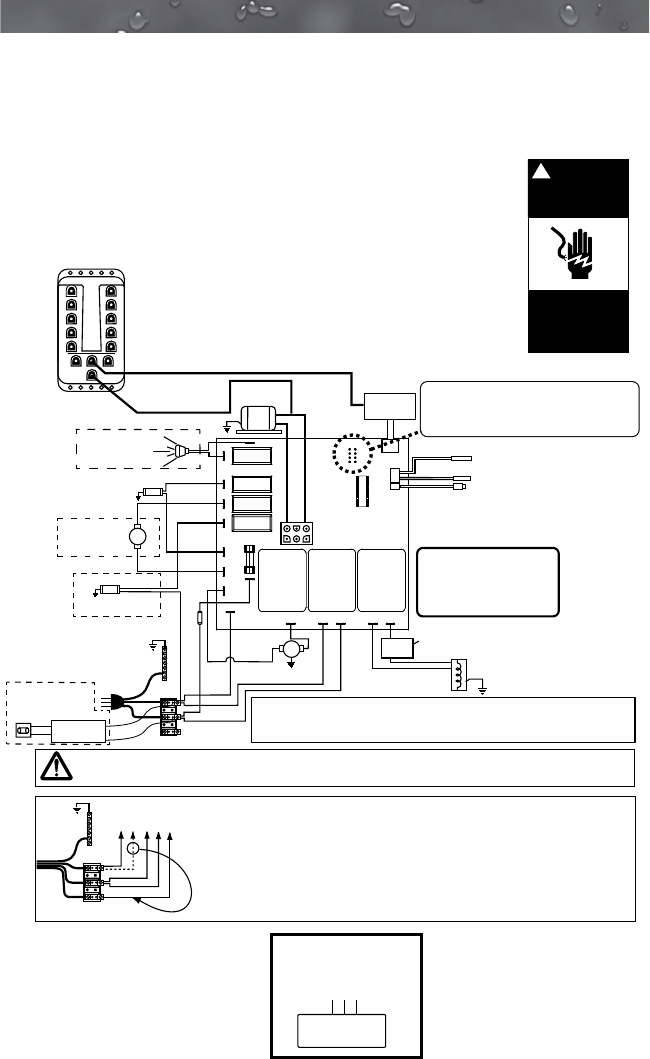
16.2 North American J-315 and J-325 Convertible Power Models
(60 Hz)
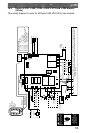
This wiring diagram is used for all North American 120/240V 60 Hz
convertible power models.
Note: Optional 120/240 VAC 4-wire connection enhances heater output
from 1kW to 4kW.
DANGER
Turn power off
before servicing. This
task should only be
performed by a quali-
fied technician.
!
RISK OF SHOCK OR
ELECTROCUTION!
Ports 1-10
power spa
lights, waterfall
lights and step
lights on
applicable
models
Light DCU
1
2
3
4
5
6
7
8
9
10
POWER
EXP BAR EXP BAR
CLEARRAY
Standard 120 VAC 3-Wire Connection (60 Hz, 1 Phase, 15A Service),
USE COPPER CONDUCTORS ONLY. WIRE SIZE MUST MEET NEC RECOMMENDATIONS
AND/OR LOCAL CODES AND IS DETERMINED BY MAXIMUM CURRENT DRAW AND
LENGTH OF RUN.
WHT
WHT
WHT
WHT
WHT
WHT
BLK
BLK
BLK
BLK
BLK
BLK
BLK
BLK
BLK
RED
RED
*
RED
*
RED
*
RED
Heater
1.0 kW @ 120 VAC (3-wire connection)
4.0 kW @ 240 VAC (4-wire connection)
Pressure Switch
Hi-limit/Freeze Sensor
Temperature Sensor
J2
J3
F1
20A
250V
SC-20
Main Pump
Transformer
120 VAC
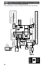
Use copper conductors ONLY. Wire size must be appropriate per NEC and/or local codes.
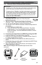
Optional 4-Wire 240/120 VAC Convertible Heater Connection
1. Remove and discard the factory installed GFCI Cord.
2. Move
RED* wire from TB1 position #1 to TB1 position #3 as shown.
3. Permanently connect to the power supply.
4. If hot tub is to be operated on 30A service, make sure the jumper provided at location JP1 #1 & 2 on the circuit board is installed.
If hot tub is to be operated on 40A service, remove the jumper JP1 #1 & 2 on the circuit board.
HI
J1 Logic Jumper Settings
JP1 1-2 ON = 30A Logic (4-wire 120/240 VAC operation only)
JP1 1-2 OFF = 40A Logic (4-wire 120/240 VAC operation only)
JP1 7-8 ON = °C Temperature Display
JP1 7-8 OFF = °F Temperature Display
This device complies with Part 15 of the
FCC rules. Operation is subject to the
following two conditions:
1. This device may not cause harmful
interference.
2. This device must accept any inteference
received including interference that may
cause undesired operation.
J20
J21
J12
J14
J16
J11
J15
J13
J17 J7 J8
J9
J10
J5
J6
Heater IN Heater OUT
F1
K5 K7 K8
J1
Control
Panel
7
5
3
1
8
6
4
2
To circuit bo
ard
GRN
TB1
WHT
BLK
3
2
1
3
2
1
GROUND
GRN
TB1
WHT
BLK
RED
GROUND
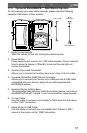
WARNING, ELECTRICAL SHOCK HAZARD EXISTS!
Hard
Wire
Only
Plug-in
GFCI
Cord (US
Models
Only) OR
Hard
Wire
EXTERNAL SERVICE PANEL
BOX DISCONNECT MEANS
MUST BE LOCATED NO CLOSER
THAN 5 FT. (1.52m) FROM THE
INSIDE WALLS OF THE SPA AND
WITHIN SIGHT OF SPA
MAIN POWER
ON//OFF SHUTOFF
SWITCH
C
Circ.
Pump
(Not offered
on all models)
THERM
SWITCH
(Located inside the heater for certain models)
Control
Panel
Always remove power to spa before wiring and/or configuring the circuit board.
Mini-Din Cable provides
constant 12VAC from
yellow transformer wires
Mini-Din Control
Panel Cable
(Not offered on all models)
BLK
WHT
OZONE
STEREO
POWER SUPPLY
(Not offered on all models)
(Not offered on all models)
SPA LIGHT