


16
J-300
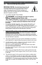
7. The electrical circuit supplied for the spa must include a suitable
ground fault circuit interrupter (GFCI) as required by NEC/USA Article
680-42.
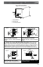
8. To gain access to the spa’s power terminal block, press the release
button securing the synthetic cabinet panel under the control panel
(Figure A). Then remove the four control box door screws and door
(Figure B).
9. Select the power supply inlet you want to use (Figure A). Feed power
cable to control box, then install it through the large opening provided
in the bottom side of the box.
10. Connect wires, color to color, on terminal blocks TB1 and TB3
(Figure C, page 17). TIGHTEN SECURELY! All wires must be
hooked up securely or damage could result.
11. Install control box door and screws and reinstall the cabinet panels.
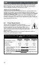
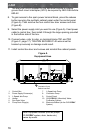
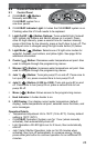
Figure A
Equipment Area
Note: Equipment location (such as pumps,
CLEARRAY system, drain, heater etc.)
varies by model.
Circulation Pump
Behind Load Box
5
4
3
7
1
2
2
9
6
6
10
11
8
1. Control Box
2. Power Supply Entrance(s)
3. 1-Speed Jets Pump
4. Heater
5. Spa Drain Valve
6. Pump Drain Plugs(s)
7. 1-Speed Jets Pump
8. Circulation Pump
9. Control Panel
10. CLEARRAY® (Ultraviolet) Water
Purication System
11. Electronic Ballast (for the CLEARRAY
System)