


SERVICE AND ADJUSTMENT
Sitting on the seat, in the operators position,
press both control levers forward. If both control
levers line up with each other, then no
adjustment is needed. If they do not line up,
follow instructions below.
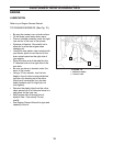
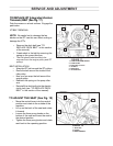
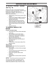
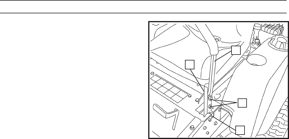
TO ADJUST CONTROL LEVERS
(See Fig. 19)
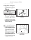
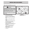
TO REMOVE WHEELS FOR
REPAIR
REAR TIRES
IMPORTANT: Block front tires to prevent the
mower from rolling.
• Park mower on a level surface and apply
park brake.
• Jack up the rear end of the mower on the
side of the damaged tire.
• Remove 4 lug nuts to allow wheel
removal.
• Repair tire.
• Reassemble in reverse order of previous
steps.
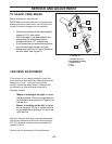
• Park mower on a level surface and apply
park brake.
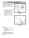
• Jack up the front end of the mower.
• Using a 3/4" wrench and/or socket w/
drive ratchet, remove hex nut and hex
bolt from the caster fork.
• Remove the tire from the fork.
• Remove the spacer from the inside of
the caster rim.
• Repair tire
• Reassemble in the reverse order of the
previous steps.
FRONT CASTER TIRES
• Identify which control lever moves further
forward.
• Using a 9/16" wrench, slightly loosen the
bottom hex bolt (about 1/2 turn) on the
opposite control lever.
• Move both control levers to the front
again and apply more pressure to the
control lever that you loosened to bring
the two control levers in line with each
other.
• Tighten hex bolts.
NOTE: To seal tire punctures and prevent flat
tires due to slow leaks, tire sealant may be
purchased from your local parts dealer. Tire
sealer also prevents tire dry rot and corrosion.
FIGURE 19
CZ-2
1
2
3
4
1. CONTROL LEVER
2. CONTROL ARM
3. HEX BOLTS
4. NEUTRAL SLOT