


1.47 1.47
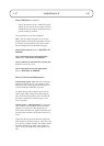
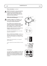
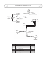
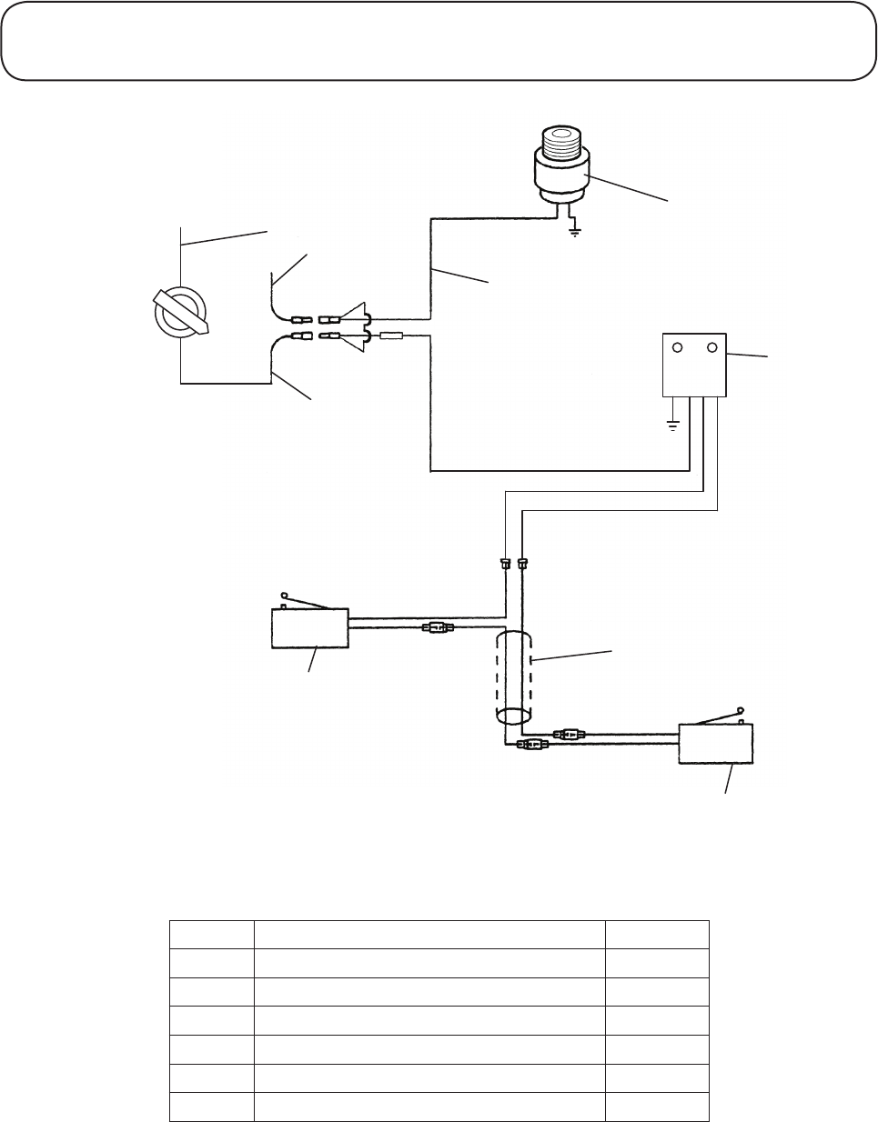
ELECTRICAL CIRCUIT DIAGRAM
Black
Black
Stop*Switch
(Mounted*on*handlebar)
Control
Module
Stop*Switch
Wire
Red
Red
Engine*Stop
Switch*Wire
Engine*Stop
Switch
(Mounted*On*
Engine)
Engine*Stop
Switch*Wire
Red
Black
On
OFF
Yellow
Yellow
Switch*Link*Wire
Red
Transmission
Microswitch
Cutter*Clutch
Microswitch
Blue
Red
Blue
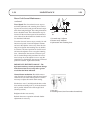
4
6
5
1
2
7
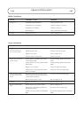
Item No. Description Part No.
1 Switch Assembly C/W Keys 510224
2 Control Module Assy 111-5820
4 Cable Assy Microswitch 510116
5 Cutterclutch Microswitch 510068
6 Transmission Microswitch 510069
7 Cable Assy Engine Stop 510227